Electronic device with placing angle sensing function and method for selecting operation mode

An electronic device and angle sensing technology, which is applied in the recording/reproducing, filament/mesh carrier operation control, instruments and other directions by optical methods, which can solve the problems of optical pickup head damage, optical disc cards, etc.

Inactive Publication Date: 2008-09-10
LITE ON IT
View PDF3 Cites 0 Cited by
  • Summary
  • Abstract
  • Description
  • Claims
  • Application Information

AI Technical Summary

Problems solved by technology

Not only that, but an upside-down optical drive can also cause the disc to jam, which in turn can cause damage to the expensive optical pickup head inside the drive

Method used


Image

  • Electronic device with placing angle sensing function and method for selecting operation mode
  • Electronic device with placing angle sensing function and method for selecting operation mode
  • Electronic device with placing angle sensing function and method for selecting operation mode

Examples


Embodiment Construction

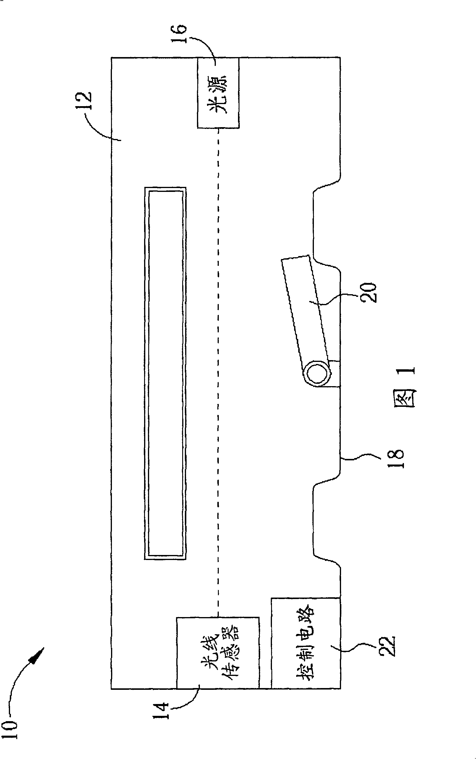
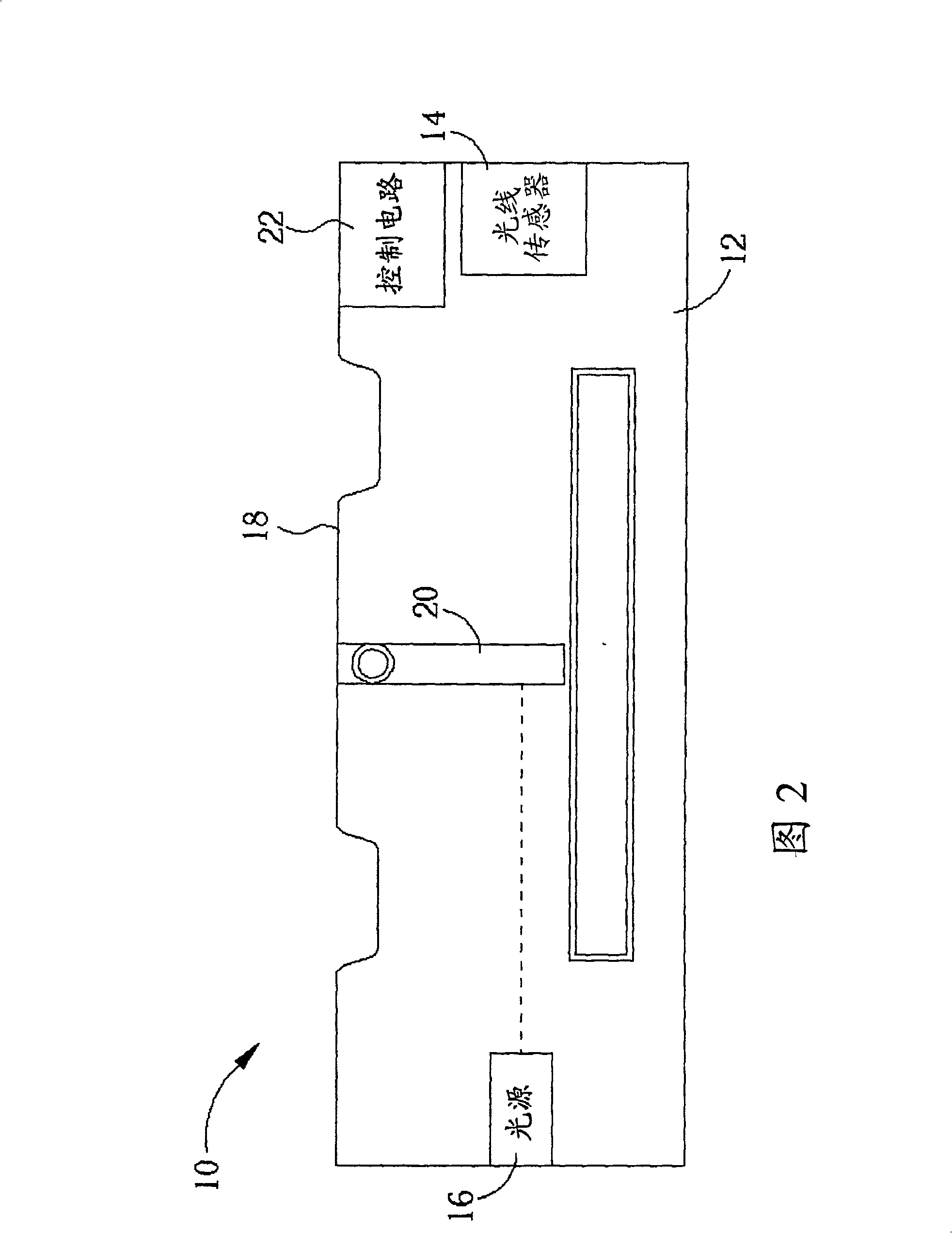
[0032] Please refer to FIG. 1 . FIG. 1 is a perspective view of a horizontally placed electronic device 10 in a preferred embodiment of the present invention. The electronic device 10 has a placement angle sensing function. The electronic device 10 includes an optical drive 12, a light sensor 14 for sensing light, a light source 16 for emitting light toward the light sensor 14, a housing 18, a rotatable fixed to the housing 18 and Used to rotate with the inclination of the optical drive 12 and block the light emitted by the light source 16 toward the light sensor 14 when the optical drive 12 is tilted to an angle within a predetermined range, and a light blocker 20 electrically connected to the light sensor 14 and the control circuit 22 used to control the operation of the optical drive 12 according to whether the light sensor 14 receives the light emitted by the light source 16, wherein the light blocker 20 can cause different angles when the optical drive 12 is tilted to diff...


PUM


Abstract

The electronic device with setting angle sensing function includes one electronic assembly, one light sensor for sensing light, one light source to emit light to the light sensor, one light obstruct unit to obstruct light from the light source when the electronic device is inclined within some preset angle range, and one control circuit connected to the light sensor to control the electronic device for selecting one from several operation modes based on the strength of the sensed light.

Description

technical field [0001] The present invention relates to an electronic device, in particular to an electronic device with a placement angle sensing function. Background technique [0002] In recent years, due to the rapid development of digital technology, various analog data such as images and sounds can be converted into digital data for subsequent storage or transmission processing. With the increasing demand for storage space for digital data, the past data storage media, such as tapes or magnetic disks, have long been insufficient, replaced by optical discs, and optical drives are used to access an optical disc. An electronic device that stores digital data. [0003] Generally speaking, the optical drive needs to be in a horizontal state to correctly read the data stored in the optical disc. In other words, if the optical drive is already in a non-horizontal state, such as upside down, but continues to read the optical disc without knowing it, At this time, the data re...

Claims


Application Information

Patent Timeline
Patent Type & Authority Patents(China)
IPC IPC(8): G11B7/13G11B15/16
Inventor 林瑞江
Owner LITE ON IT
Why Eureka
Try Eureka