Unlock instant, AI-driven research and patent intelligence for your innovation.

Monitoring system

A monitoring system and camera technology, applied in the field of monitoring systems, can solve the problems of high cost such as being unable to adapt to changes, increasing the dead angle of the monitoring area, setting up engineering fees or management fees, etc.

Inactive Publication Date: 2008-10-15
HITACHI LTD
View PDF8 Cites 0 Cited by
  • Summary
  • Abstract
  • Description
  • Claims
  • Application Information

AI Technical Summary

Problems solved by technology

[0004] In the defense systems described in the above-mentioned Japanese Patent Application Laid-Open No. 2002-298260 and Japanese Patent Laid-Open No. 2003-109155 , although the security camera is used, the sending device and the image processing unit specify the suspect to contribute to the initial investigation, but the security camera device Large by itself and requires significant expense in terms of setup
In addition, since a network connection is necessary to report the operation information of the transmitting device, and a monitor device for checking the event status is required, the overall system is very large, and the cost such as installation engineering costs and management costs is high
[0005] If the cost is reduced, the number of installations of security cameras will be limited, and the surveillance area will be limited, resulting in increased blind spots in the surveillance area.
In addition, since it is connected to a monitor device, it gives pedestrians an unpleasant feeling that they are always being watched
Once the security camera is set up, it is not easy to move, and it cannot adapt to changes in the surrounding environment

Method used


Image

  • Monitoring system
  • Monitoring system
  • Monitoring system

Examples


Embodiment Construction

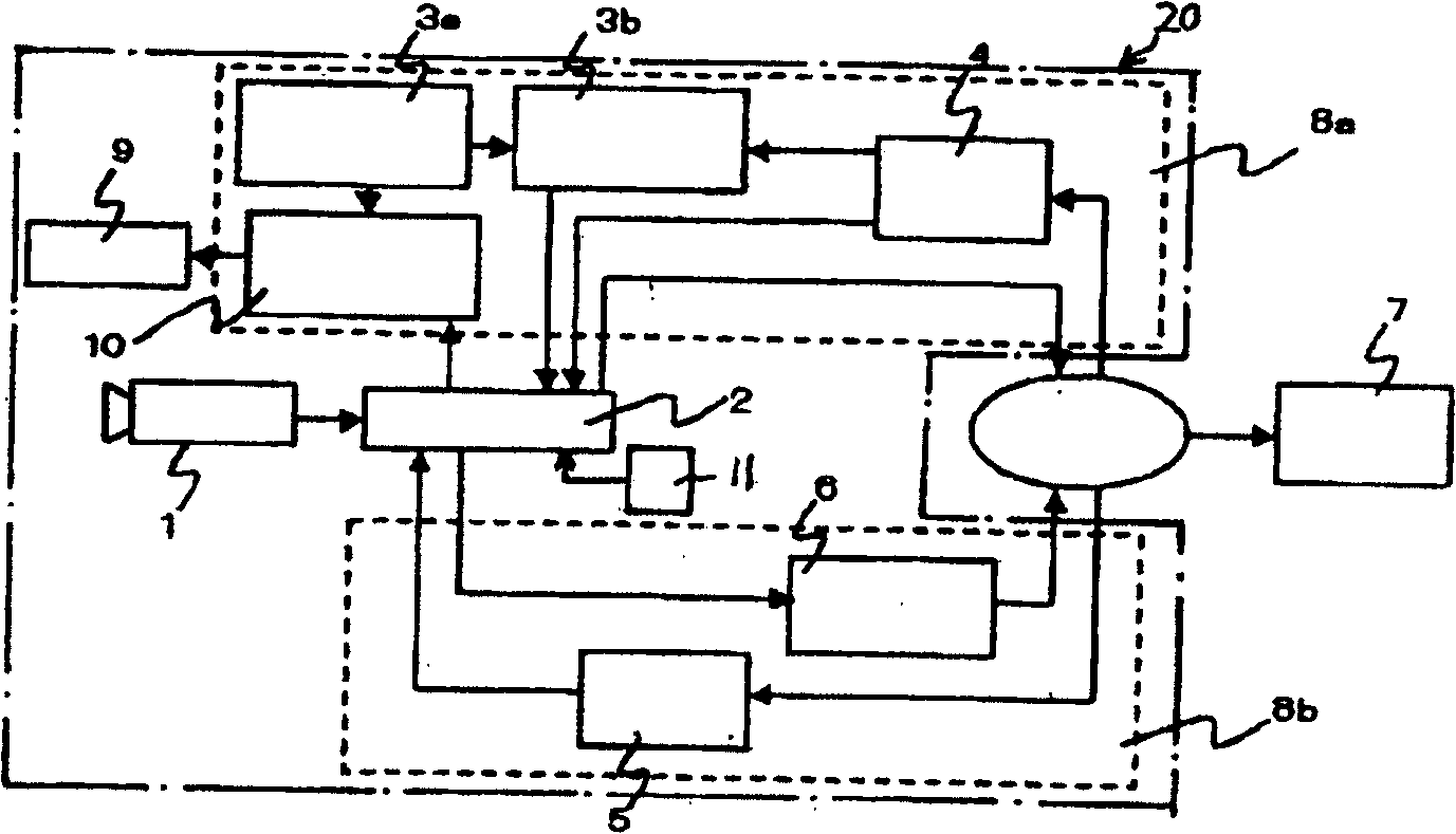
[0014] Below, use Figure 1 to Figure 6 Several embodiments of the monitoring system of the present invention will be described. figure 1 is the block diagram of the monitoring system, figure 2 It is a pattern diagram of the monitoring system. in the figure 2 In this example, a plurality of surveillance cameras are installed on a street to be monitored. The monitoring camera 20 has an imaging device 1 that captures a surveillance area, and a storage unit 2 that stores image information captured by the imaging device 1 .

[0015] The image information captured by the imaging device 1 is identified using the unique identification number storage unit 3a, the unique identification number writing unit 3b, and the unique identification number comparison unit 10 included in the storage unit detachable collection unit 8a. The storage unit detachable recovery unit 8 a also has a storage unit detachment unit 4 that physically recovers the storage unit 2 storing image information f...


PUM


Abstract

The invention provides a monitoring system equipped with imaging devices for imaging a monitoring region. Each of the imaging devices has storage device for storing image information. A unique identification number (ID) for identifying a picked-up image is assigned to each of the imaging devices. The picked-up image is retrieved, together with the associated ID, from the storage device by detaching the storage device or accessing the storage device in a non-contact manner.

Description

technical field [0001] The present invention relates to a monitoring system for monitoring city safety. Background technique [0002] An example of a security camera system for improving urban security is described in Japanese Unexamined Patent Publication No. 2002-298260. In this publication, a plurality of security devices including lighting lamps, emergency call switches, and emergency alarm equipment including security cameras are connected by a network. Thereby, incidents caused by hooligans or stalkers can be detected early and prevented. [0003] Another example of a security camera system for securing urban security is described in Japanese Unexamined Patent Publication No. 2003-109155. In this communiqué, a wide area is monitored while reducing the labor required for monitoring in a monitoring area. Moreover, when a crime occurs, it receives a transmission from a human-operated transmission device, performs image processing on the time-series image group of the s...

Claims


Application Information

Patent Timeline
Patent Type & Authority Patents(China)
IPC IPC(8): H04N7/18H04N5/225G08B13/196G08B25/00
CPCG08B13/19663G08B25/009G08B13/19656G08B13/19673G08B13/19695G08B13/19645G08B13/19684H04N7/181
Inventor 关健太滨田朋之寺本律
Owner HITACHI LTD
Features
  • R&D
  • Intellectual Property
  • Life Sciences
  • Materials
  • Tech Scout
  • Unparalleled Data Quality
  • Higher Quality Content
  • 60% Fewer Hallucinations
Learn More