Braking device for motorcycle

一种制动装置、摩托车的技术,应用在制动器等方向,能够解决差增加、时间延迟、操作量会进一步增加等问题,达到防止制动感觉的恶化、制动感觉改善、避免成本的提高的效果

Inactive Publication Date: 2008-11-26
HONDA MOTOR CO LTD
View PDF5 Cites 0 Cited by
  • Summary
  • Abstract
  • Description
  • Claims
  • Application Information

AI Technical Summary

Problems solved by technology

[0005] However, in this brake device, there may occur a time delay from the detection of the operation amount of the brake operating portion to the change of the hydraulic pressure of the wheel brake device.
Therefore, when the time delay increases, when the hydrostat is controlled based on the operation amount of the brake operation portion, the actual operation amount of the brake operation portion further increases, resulting in the target control pressure of the hydrostat and the wheel brake The difference between the actual brake pressure of the device increases
Therefore, from the driver's point of view, when the control of the hydrostat is continued from this state, it is not preferable that the controlled hydrostat suddenly increases the pressure to compensate for the aforementioned difference.

Method used


Image

  • Braking device for motorcycle
  • Braking device for motorcycle
  • Braking device for motorcycle

Examples


Embodiment Construction

[0049] Next, an embodiment of the present invention will be explained in conjunction with the accompanying drawings.

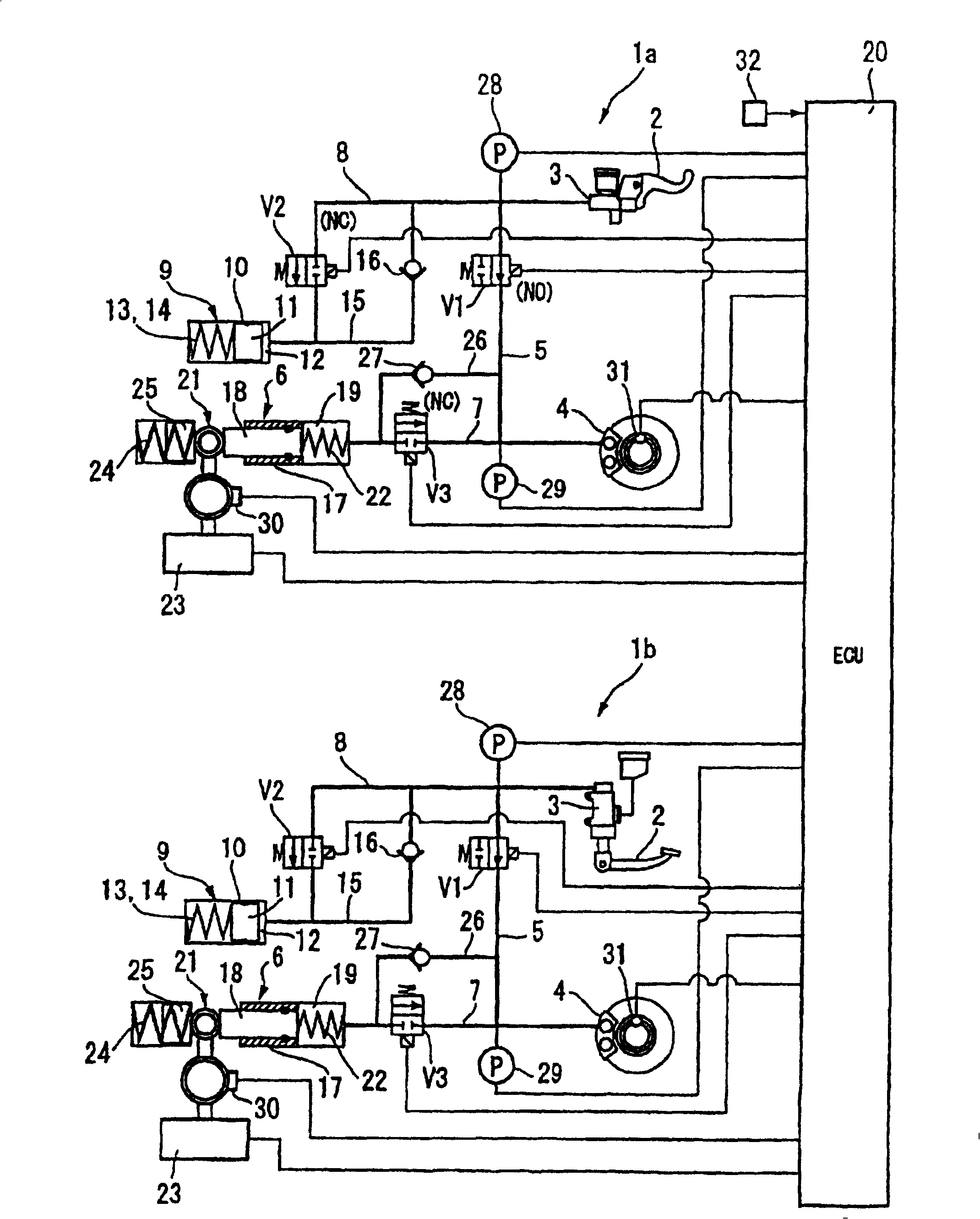
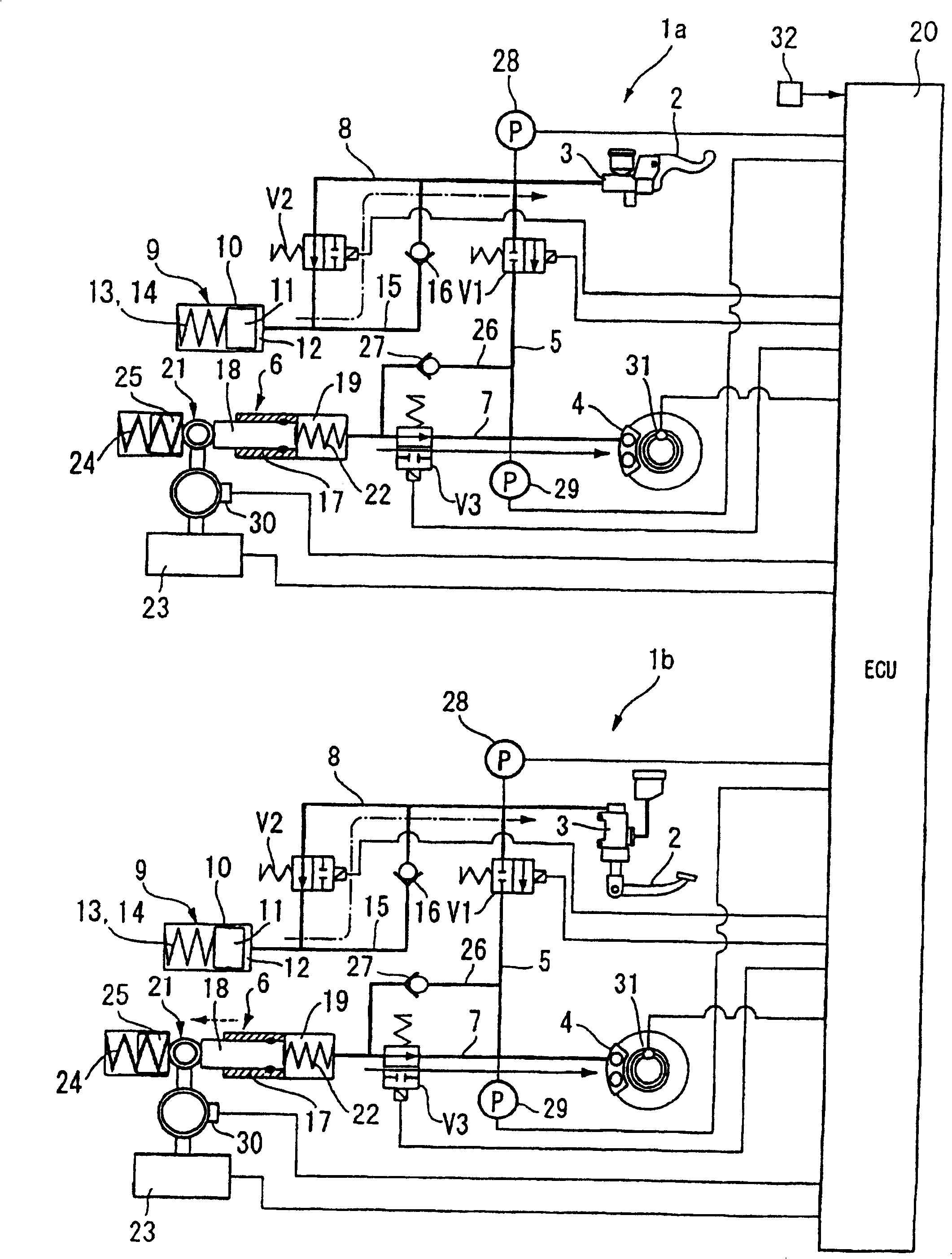
[0050] attached figure 1 It is the hydraulic circuit diagram of the motorcycle braking device of the embodiment of the present invention. In the brake device of this embodiment, the front wheel side brake circuit 1a and the rear wheel brake circuit 1b which are independent from each other are connected together through one controller (ECU) 20 .

[0051] In the front wheel side brake circuit 1a, the brake lever as the brake operating part 2 performs a braking operation, while in the rear wheel side brake circuit 1b, the brake pedal as the brake operating part 2 performs a braking operation. a brake operation. The other components are basically the same in the front-wheel-side brake circuit 1a and the rear-wheel-side brake circuit 1b. Therefore, only the brake circuit 1a on the front wheel side will be described in detail, and the same parts in the brake circ...


PUM


Abstract

A braking device for a motorcycle for controlling a sudden increase in the braking force caused by a time lag from the time the amount of operation of a brake operating portion is detected until a change in hydraulic pressure of wheel braking means for improving the feel of braking. An input-side pressure sensor detects a master cylinder pressure and a hydraulic modulator creates a hydraulic pressure to be exerted on a brake caliper. A controller is provided for controlling the hydraulic pressure created by the hydraulic modulator in accordance with a detected signal provided from the input-side pressure sensor. In accordance with a change in the quantity per unit time of the detected signal provided from the input-side pressure sensor the controller limits a change speed of the hydraulic pressure created by the hydraulic modulator.

Description

technical field [0001] The present application relates to a braking device for motorcycles, more particularly to a so-called brake-by-wire braking device. Background technique [0002] A brake-by-wire device for a motorcycle is known in which the operation amount of a brake operating portion such as a brake lever is electrically detected, and the operation of the wheel brake device is generated based on the detected value using a hydraulic regulator. achieved by hydraulic pressure. For example, see JP-A 310717 / 2001. [0003] A brake-by-wire device is known in which a master cylinder is interlocked with a brake lever (brake operating portion) and a brake caliper (wheel brake device) for hydraulically operating a braking force on a wheel, which are set The main brake passages with normally open first electromagnetic switch valves are connected together. The hydraulic regulator is used to supply the hydraulic pressure generated by the electric actuator to the brake caliper, ...

Claims


Application Information

Patent Timeline
Patent Type & Authority Patents(China)
IPC IPC(8): B60T8/74
Inventor 中山昌宣竹之内和也谷一彦加藤正家
Owner HONDA MOTOR CO LTD
Why Eureka
Try Eureka