Impeller mechanical wing profile with suction edge injection

An impeller machinery and suction technology, applied in mechanical equipment, engine components, machines/engines, etc., can solve problems such as affecting the performance of downstream blades, large penetration rate, uneven gas distribution, etc., to achieve simple structure and reduce penetration rate. , the effect of uniform flow

Inactive Publication Date: 2009-03-18
SHANGHAI JIAOTONG UNIV
View PDF5 Cites 0 Cited by
  • Summary
  • Abstract
  • Description
  • Claims
  • Application Information

AI Technical Summary

Problems solved by technology

However, it has disadvantages: the small holes are equal in diameter, so that the gas ejected from the small holes is distributed unevenly along the height of the blade. In addition, the small holes are in a circular structure, and the ejected gas forms a horseshoe vortex structure with the mainstream, which affects the downstream blades. performance, and the penetration rate of the small-hole jet stream in the main flow is greater

Method used


Image

  • Impeller mechanical wing profile with suction edge injection
  • Impeller mechanical wing profile with suction edge injection
  • Impeller mechanical wing profile with suction edge injection

Examples


Embodiment Construction

[0023] The embodiments of the present invention are described in detail below in conjunction with the accompanying drawings: this embodiment is implemented on the premise of the technical solution of the present invention, and detailed implementation methods and specific operating procedures are provided, but the protection scope of the present invention is not limited to the following the described embodiment.

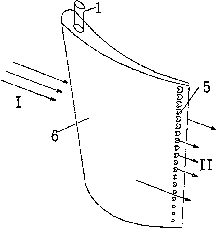
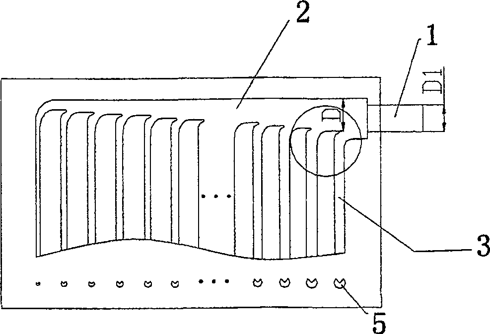
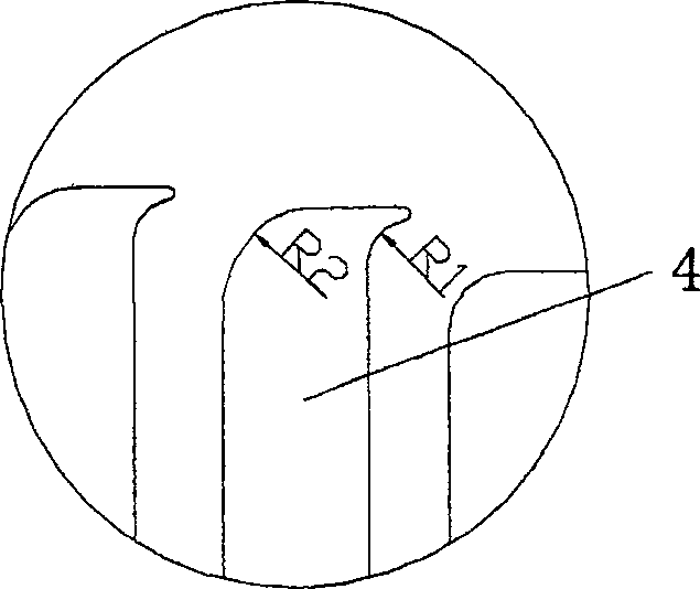
[0024] Such as figure 1 As shown, this embodiment includes: control gas input pipe 1, gas main flow channel 2, gas branch flow channel 3, flow guide member 4, suction side air injection hole 5, airfoil body 6, and the connection relationship is: inside the airfoil body 6 It is a cavity, the gas main channel 2 and the gas branch channel 3 are placed in the cavity, the control gas input pipe 1 is placed outside the airfoil body 6, one end of the control gas input tube 1 communicates with the end of the gas main channel 2, and the gas main channel 2 The other end commun...


PUM


Abstract

The invention relates to a wing for an impeller with suction-edge jetting in the technical field of impeller, which comprises a wing body, an inputting pipe for the controlling gas, a main gas passageway, branch gas passageways, diversion components, and suction-edge jetting holes. The inner of the wing body is a cavity, the main gas passageway and the branch gas passageways are in the cavity; the inputting pipe for the controlling gas is located outside the wing body; one end of the inputting pipe for the controlling gas is communicated with the main gas passageway, another end is communicated with the branch gas passageways; between the branch gas passageways, diversion components are provided. The suction-edge jetting holes are provided with a segment lobe each, so that the suction-edge jetting holes are of segment structure. The suction-edge jetting holes are arranged at the suction edge of the wing body near to the tail edge in an equi-spaced way, the diameters of the suction-edge jetting holes are arranged in arithmetic progression along the tail edge of the wing body. The invention fills the speed loss of the tail edge of the wing body, reduces the speed pulse at the tail area, reduces the tail width of the wing, and drops the interference noise.

Description

technical field [0001] The invention relates to an airfoil in the technical field of turbomachinery, in particular to a turbomachinery airfoil with suction side jetting. Background technique [0002] Impeller machinery is not only widely used in various production sectors of the national economy such as energy and power, chemical petroleum, mining metallurgy, transportation, building air conditioning, food and medicine, water conservancy engineering, etc., and is closely related to people's daily life; There are also important uses. Such a wide range of applications makes turbomachinery occupy an important position in the national economy and national defense construction, and thus attracts people's attention to the performance of turbomachinery. At the same time, the operation of turbomachinery, especially the high-decibel noise produced by aeroengines affects people's normal life, and the noise problem of turbomachinery is also increasingly concerned by people. Therefore,...

Claims


Application Information

Patent Timeline
Patent Type & Authority Patents(China)
IPC IPC(8): F04D29/44F01D9/02
Inventor 吴亚东竺晓程欧阳华杜朝辉
Owner SHANGHAI JIAOTONG UNIV
Why Eureka
Try Eureka