Water-saving tap

A faucet and water saver technology, applied in valve details, filter separation, sliding valve, etc., to achieve the effect of simple operation and cleaner cleaning

Inactive Publication Date: 2009-06-17
张金辉
View PDF5 Cites 0 Cited by
  • Summary
  • Abstract
  • Description
  • Claims
  • Application Information

AI Technical Summary

Problems solved by technology

[0002] The current taps include ceramic valve cores, ball valves, water mixing valves, etc. Water saving can be realized by adjusting the size of the water gate, but it mainly depends on people's awareness and cannot effectively solve the problem of water saving fundamentally.

Method used


Image

  • Water-saving tap
  • Water-saving tap
  • Water-saving tap

Examples


Embodiment Construction

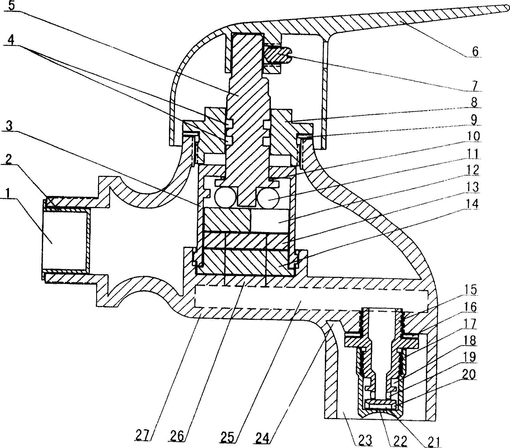
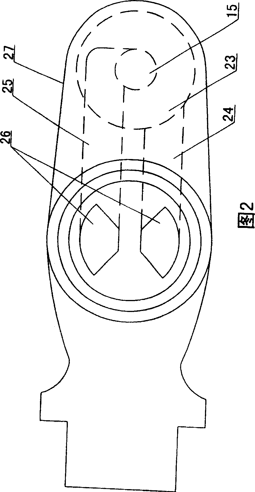
[0016] Such as figure 1 As shown in -4, the faucet body 27 is hollow, the bottom of the faucet body 1 is provided with water-saving and water-discharging double holes 26, and the water-saving and water-discharging double holes 26 are provided with a water-saving channel 25 and a water-discharging channel 24, and the valve core 3 is placed in the water-saving and water-discharging double holes. 26 above, the lower end of the spool 3 is provided with a gasket 14, the fixed piece 13 is placed above the gasket 14, the moving piece 127 is placed above the fixed piece 13, the control rod 5 is placed above the moving piece 12, the sealing gasket 14 and the fixed piece 13 are both There are double holes corresponding to the double holes 26 for saving and releasing water, the moving plate 12 is set with a fan-shaped hole, the middle part of the regulating rod 5 is set with a sealing ring 4, the upper end is fastened with the handle 6 by the screw 7, the valve core pressure cap 8 is conn...


PUM


Abstract

The present invention relates to a water-saving running water tap. Said water-saving running water tap includes the following several portions: hollow tap body, water-saving channel, water-draining channel, water-saving device, valve core, sealing plate and fixed piece. Said invention also provides the connection mode of all the above-mentioned portions. Said invention is a multifunctional tap integrating the functions of spraying, flushing and draining into one body.

Description

technical field [0001] The invention belongs to the field of tap water appliances, in particular to a multifunctional water-saving faucet. Background technique [0002] The current water taps include ceramic valve cores, ball valves, mixing valves, etc. Water saving is realized by adjusting the size of the water gate, but it mainly depends on people's awareness and cannot effectively solve the problem of water saving fundamentally. Contents of the invention [0003] The technical problem to be solved by the present invention is: to overcome the deficiencies of the prior art, to provide a water-saving faucet that integrates spray washing, flushing and water discharge, and is used in washing places such as kitchens, toilets, hotels, etc., and can save water by more than 70%. . [0004] In order to solve the above technical problems, the technical solution adopted in the present invention is: a water-saving faucet, including a faucet body, a control rod, a water inlet, a fau...

Claims


Application Information

Patent Timeline
Patent Type & Authority Patents(China)
IPC IPC(8): F16K3/08F16K47/00B01D35/04
Inventor 张金辉
Owner 张金辉
Why Eureka
Try Eureka