

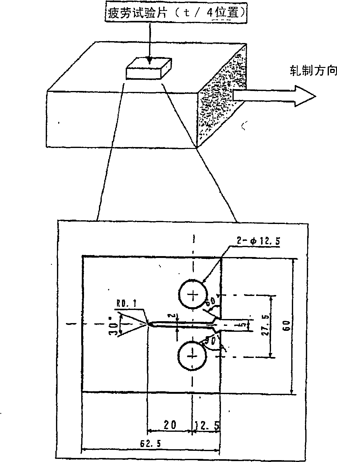
Fatigue cracking resistant expansibility excellent steel plate
A scalable and fatigue-resistant technology, applied in the field of steel plates, which can solve the problem that the dispersion state of retained austenite is not disclosed in the slightest
- Summary
- Abstract
- Description
- Claims
- Application Information
AI Technical Summary
Problems solved by technology
Method used
Image

Examples
Embodiment 1
[0213] Example 1 (invention example and comparative example related to the first embodiment of the present invention)
[0214] According to the usual smelting method, after smelting the steel having the composition shown in Tables 1 and 2 into a slab, it is heated to the temperature shown in Tables 3 and 4 (expressed as "heating temperature" in Tables 3 and 4), This is followed by hot rolling and finish rolling. In Tables 3 and 4, the finish rolling temperature (expressed as "end temperature" in Tables 3 and 4) and the reduction rate to reach the finish rolling temperature + 50°C (expressed as "reduction rate" in Tables 3 and 4) are shown. "). Then after finish rolling, cooling to the temperature for ferrite transformation (in Tables 3 and 4 expressed as "holding temperature") for a specified time (expressed as "holding time" in Tables 3 and 4). After the ferrite phase transformation, cool at the cooling rate shown in Tables 3 and 4 (expressed as "second cooling rate" in Ta...
Embodiment 2
[0234] Example 2 (invention example and comparative example related to the second embodiment of the present invention)
[0235] According to the usual smelting method, the steel (No.1-30 of Example 2) with the composition shown in Tables 7 and 8 is smelted to become a steel slab, and after being heated to the low temperature γ region below Ar3+50°C, it is quenched to Below 300°C, after two pre-rolling treatments to generate martensite or bainite, the conditions shown in Table 9 (each heating temperature, finish rolling temperature, reduction in low temperature γ range (multiple finish rolling) temperature +50°C to the reduction of the final rolling temperature), the cooling rate after rolling (the first cooling), the cooling stop temperature, the holding time to this temperature and the cooling rate after the holding (the second cooling) By reheating, rolling, and cooling, high-tensile steel sheets having the thicknesses shown in Table 9 were produced.
[0236] [Table 7] (mas...
Embodiment 3
[0262] Example 3 (present invention example and comparative example concerning the third embodiment of the present invention)
[0263] Steels having the compositions shown in Tables 12 and 13 were melted into slabs and then hot-rolled according to a usual melting method. The reduction rates at temperatures up to 950° C. are shown in Tables 14 and 15 (expressed as “Reduction Rates” in Tables 14 and 15). After hot rolling, cool to a specified temperature (expressed as "first stop temperature" in Tables 14 and 15) at the cooling rate shown in Tables 14 and 15 (expressed as "first cooling rate" in Tables 14 and 15) ), hold for a specified time (expressed as "hold time" in Tables 14 and 15). Thereafter, the steel sheets were cooled to 200°C or lower at the cooling rates shown in Tables 14 and 15 (expressed as "second cooling rates" in Tables 14 and 15). Also, the cooling was stopped on the way of cooling to below 200°C, and the temperature was recorded in the column of "second st...
PUM
| Property | Measurement | Unit |
|---|---|---|
| particle diameter | aaaaa | aaaaa |
| particle diameter | aaaaa | aaaaa |
| particle diameter | aaaaa | aaaaa |
Abstract
Description
Claims
Application Information