High power LED module for spot illumination

A technology of light-emitting modules and light-emitting diodes, which is applied to the components of lighting devices, cooling/heating devices of lighting devices, lighting devices, etc., can solve the problems of high-power LED lamp inclusion, etc., to increase the working life and reduce the working temperature Effect

Inactive Publication Date: 2009-08-05
GELCORE LLC (US)
View PDF4 Cites 0 Cited by
  • Summary
  • Abstract
  • Description
  • Claims
  • Application Information

AI Technical Summary

Problems solved by technology

However, this is only a planar approach, in which case the PCB is not directly integrated into the heat sink fixture included in the lamp body
Therefore, it is not possible to include high power LED lamps in MR packages

Method used


Image

  • High power LED module for spot illumination
  • High power LED module for spot illumination
  • High power LED module for spot illumination

Examples


Embodiment Construction

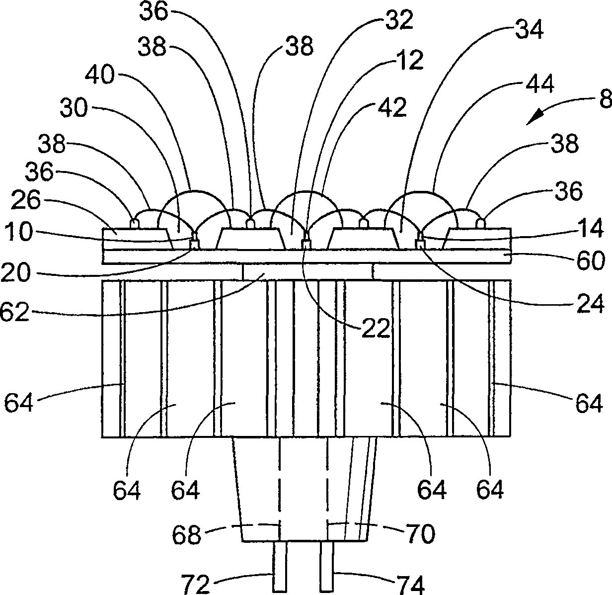
[0022] refer to figure 1 , device 8 includes an integrated array of high power LEDs 10, 12, 14 mounted to respective electrical insulator submounts 20, 22, 24, respectively. The submounts 20 , 22 , 24 are secured to a metal backside substrate 26 within respective wells 30 , 32 , 34 . Alternatively, the LEDs 10, 12, 14 are secured directly to the metal substrate 26, thereby eliminating the need for a submount. The wells 30, 32, 34 in which the LEDs 10, 12, 14 are located are typically stamped or drilled directly into the substrate material so as to preferably form a "reflector" shape. However, other LED and well configurations are also foreseen. The submounts 20, 22, 24 (or alternatively the LEDs 10, 12, 14) are secured by a highly thermally conductive material such as solder, filled epoxy, heat tape, and / or other materials with good thermal conductivity. adhesive) to the backside substrate 26 as a heat sink. LEDs 10 , 12 , 14 are connected to electrical contacts 36 by cond...


PUM


Abstract

A light-emitting module includes a light-emitting diode assembly, which is provided with a front-side light-emitting diode array and a rear side. The rear side is in thermal communication with a thermally conductive extension sheet, and a thermally conductive core is in thermal communication with the conductive extension sheet. The thermally conductive core includes an electrical conductor in operative communication with the front LED array, and a plurality of appendages positioned around the thermally conductive core so that they are in thermal communication with the conductive extensions.

Description

technical field [0001] The present invention relates generally to light emitting diode (LED) technology for lighting applications. It finds particular application in relation to spot module illumination applications and is described with particular reference thereto. It will be appreciated, however, that the invention may also be modified for other similar applications. Background technique [0002] Current partial modular lamp technology mainly relies on halogen type lamps for microreflector (MR) and parabolic reflector (PAR) type lamp illumination. But using halogen type lamps for local lighting has some disadvantages. For example, excessive heat can limit the use of these types of lamps in commercial and consumer applications. Existing LED solutions utilize standard, off-the-shelf, epoxy-encapsulated, through-hole LED sources in the light source array. These configurations severely limit the output brightness of the lamp. Therefore, the potential market breakthroughs...

Claims


Application Information

Patent Timeline
Patent Type & Authority Patents(China)
IPC IPC(8): H01L25/075H01L33/00F21K99/00F21S2/00F21S8/04F21V5/04F21V19/00F21V29/00F21Y101/02H01L33/64
CPCH01L33/642F21V7/0083F21V29/2231Y10S362/80F21K9/137F21V29/004F21V29/2256H01L2924/0002F21Y2101/02F21V29/2287F21K9/00H01L2224/48091H01L25/0753F21V29/2281F21V29/2275F21V19/0005F21V29/767F21V29/773F21V29/81F21V7/041F21V7/06F21K9/233F21Y2115/10F21Y2113/13H01L2924/00014F21V29/74
Inventor 克里斯托弗·L·博勒尔安东尼·D·波拉德格雷格·E·伯克霍尔德詹姆士·T·彼得罗斯基马休·L·萨默斯小罗伯特·F·卡尔利切克小斯坦特恩·E·韦弗查尔斯·A·贝克尔
Owner GELCORE LLC (US)
Why Eureka
Try Eureka