Heat-dissipating device with interfacial enhancements

a technology of heat dissipation device and interfacial enhancement, which is applied in the direction of indirect heat exchanger, semiconductor/solid-state device details, lighting and heating apparatus, etc., can solve the problems of limited heat dissipation capability, limitations of heat spreader, and large heat generation of internal components, so as to reduce the thermal resistivity

Active Publication Date: 2021-11-23
QUALCOMM INC
View PDF113 Cites 0 Cited by
  • Summary
  • Abstract
  • Description
  • Claims
  • Application Information

AI Technical Summary

Benefits of technology

[0006]Certain aspects of the present disclosure provide an apparatus. The apparatus generally includes first means for spreading heat configured to be thermally coupled to means for generating heat, second means for spreading heat, means for separating the first means for spreading heat from the second means for spreading heat, means for storing heat disposed between the means for separating and at least one of the first means for spreading heat or the second means for spreading heat and thermally coupled to at least one of the first means for spreading heat or the second means for spreading heat, and means for reducing a thermal resistivity between the means for separating and the means for storing heat. The means for separating is thermally coupled to at least one of the first means for spreading heat or the second means for spreading heat.

Problems solved by technology

Some of these internal components (e.g., a central processing unit (CPU), a graphics processing unit (GPU), and / or memory) can generate a lot of heat, especially when performing data intensive operations (e.g., processing video and / or music).
However, the heat spreader has limitations, including its limited heat-dissipating capabilities.
For example, the heat spreader implemented in a mobile device may be limited to dissipate about 3 W of heat.

Method used


Image

  • Heat-dissipating device with interfacial enhancements
  • Heat-dissipating device with interfacial enhancements
  • Heat-dissipating device with interfacial enhancements

Examples


Embodiment Construction

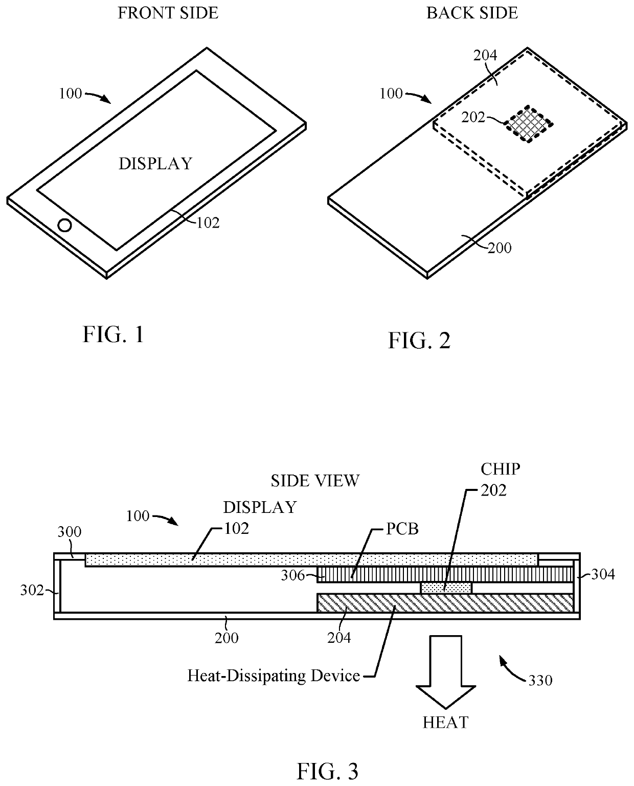
[0021]The detailed description set forth below in connection with the appended drawings is intended as a description of various configurations and is not intended to represent the only configurations in which the concepts described herein may be practiced. The detailed description includes specific details for the purpose of providing a thorough understanding of various concepts. However, it will be apparent to those skilled in the art that these concepts may be practiced without these specific details. In some instances, well-known structures and components are shown in block diagram form in order to avoid obscuring such concepts.

[0022]The various aspects will be described in detail with reference to the accompanying drawings. Wherever possible, the same reference numbers will be used throughout the drawings to refer to the same or like parts. References made to particular examples and implementations are for illustrative purposes, and are not intended to limit the scope of the dis...


PUM

PropertyMeasurementUnit
melting point/melting temperatureaaaaaaaaaa
temperatureaaaaaaaaaa

Abstract

An example heat-dissipating device with enhanced interfacial properties generally includes a first heat spreader configured to be thermally coupled to a region configured to generate heat, a second heat spreader, an interposer thermally coupled to at least one of the first heat spreader or the second heat spreader, at least one interfacial layer including a graphene material disposed on at least one surface of the interposer, and a phase change material disposed between the at least one interfacial layer and at least one of the first heat spreader or the second heat spreader and thermally coupled to at least one of the first heat spreader or the second heat spreader.

Description

BACKGROUNDField of the Disclosure[0001]The teachings of the present disclosure relate generally to a heat-dissipating device, and more particularly, to a heat-dissipating device with interfacial enhancements for an electronic device.Description of Related Art[0002]Electronic devices include internal components that generate heat. Some of these internal components (e.g., a central processing unit (CPU), a graphics processing unit (GPU), and / or memory) can generate a lot of heat, especially when performing data intensive operations (e.g., processing video and / or music). To counter or dissipate the heat generated by the CPU and / or GPU, an electronic device may include a heat-dissipating device, such as a heat spreader. As an example, a mobile device may include a heat spreader for dissipating heat generated by an integrated circuit (IC). The heat spreader may be coupled between the IC and a back side of the mobile device enabling heat generated by the IC to be dissipated through the he...

Claims


Application Information

Patent Timeline
Patent Type & Authority Patents(United States)
IPC IPC(8): F28D15/02F28F21/08H01L23/427
CPCF28D15/02F28F21/085F28F21/089H01L23/4275F28D20/02F28D2020/0008H01L23/427Y02E60/14
Inventor ANDREWS, SEAN CHARLESROSALES, JORGE LUISCHIRIAC, VICTOR ADRIAN
Owner QUALCOMM INC
Why Eureka
Try Eureka