Electric Heating Device

a heating device and heating element technology, applied in the direction of lighting and heating apparatus, heater elements, and modifications by conduction heat transfer, can solve the problems of reducing affecting the service life of the heating device, so as to ensure the dissipation of power loss. , to achieve the effect of reliable dissipation

Pending Publication Date: 2022-01-06
EBERSPACHER CATEM
View PDF0 Cites 0 Cited by
  • Summary
  • Abstract
  • Description
  • Claims
  • Application Information

AI Technical Summary

Benefits of technology

[0010]The present invention aims to specify an electric heating device that reliably ensures

Problems solved by technology

Such a dissipation of the power loss generated by the power switch to the heat sink is known from KR 10 2010 011 2035 A. However, this prior art lacks a seal between the heat sink and the interior of the control ho

Method used


Image

  • Electric Heating Device
  • Electric Heating Device
  • Electric Heating Device

Examples


Embodiment Construction

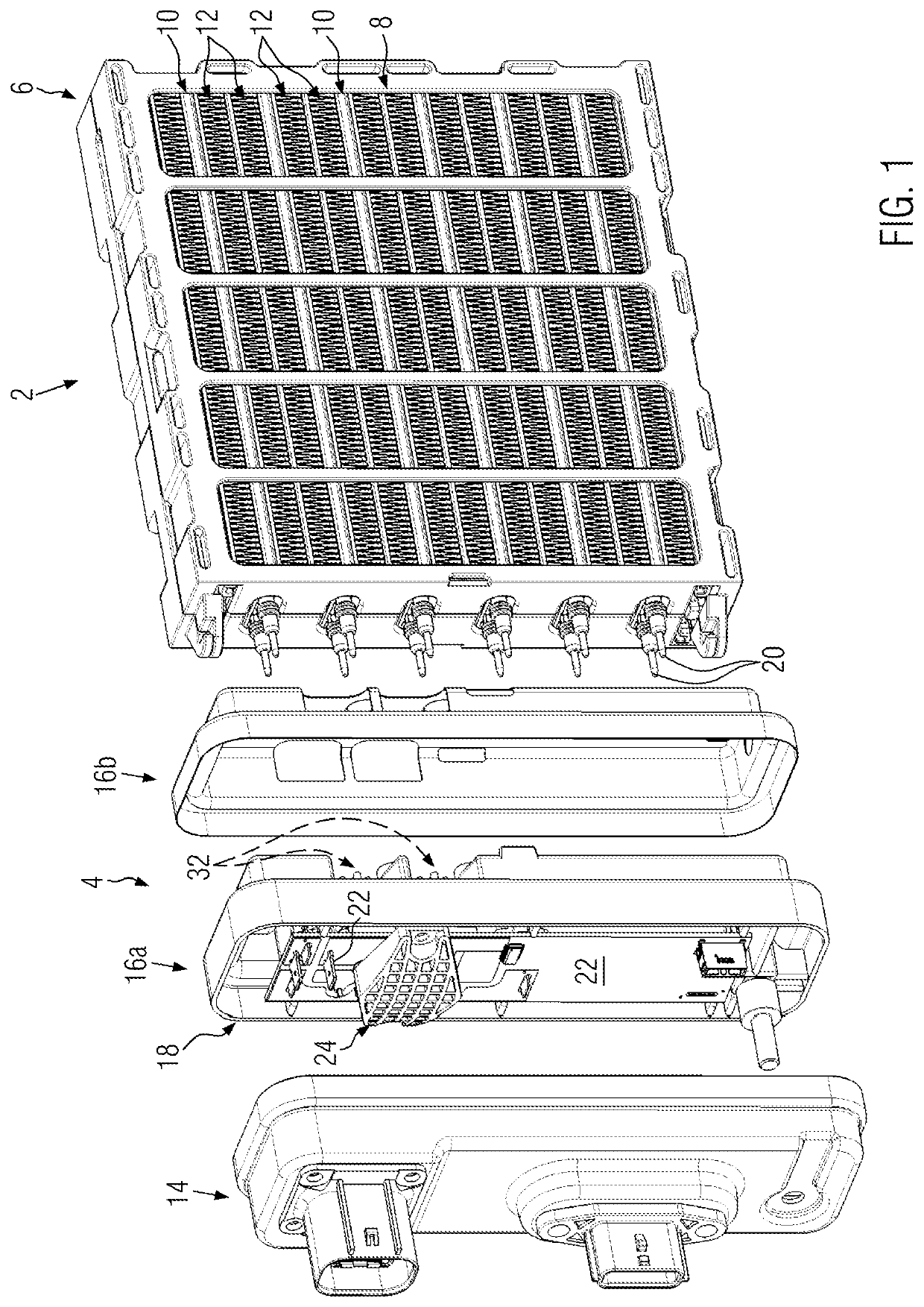
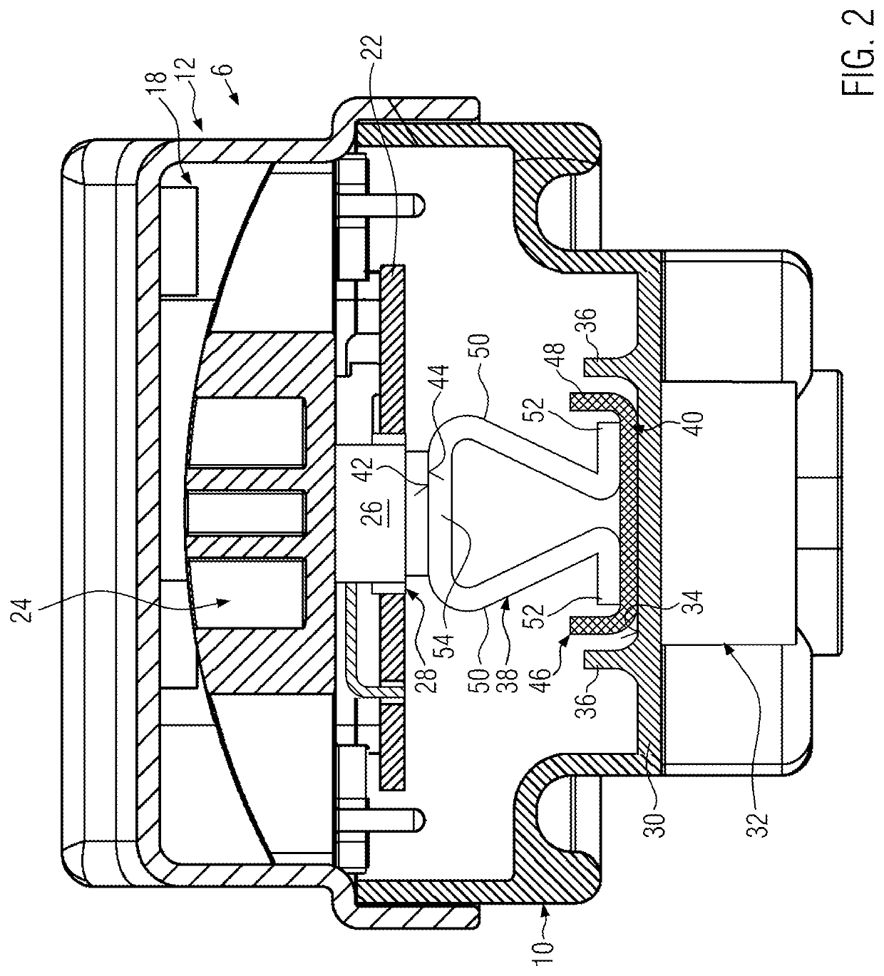
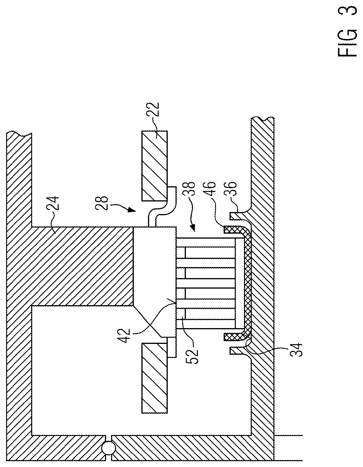
[0035]The control device 4 comprises a control housing with a housing cover 14 and a two-part housing base 16a, b. The control housing surrounds a connection chamber 18 for contact elements 20 of the PTC heating devices 10 projecting beyond the frame 6 on one side, which project into the connection chamber 18 and are electrically connected there. The electric control device 4 has an equipped printed circuit board 22 which is electrically contacted with a connection printed circuit board not shown in detail, as is known in principle from EP 2 607 121 A1. A power switch 26 is located at the level of a pressure element characterized by reference sign 24, which is partially accommodated in a bore 28 of the equipped printed circuit board 22 and partially projects beyond it in the direction of the power section. In the assembled state shown in FIG. 2, the pressure element 24 abuts against an upper side of the power switch 26. On the opposite side of the power switch 26, a partition wall 3...


PUM


Abstract

An electric heating device includes an electric control device with a control housing that is in structural unity with a housing of a power section. The power section has a frame forming a heating chamber. At least one PTC heating device with at least one PTC element and conductor elements is provided in the heating chamber. The control housing forms a chamber which is separated from the frame by a partition wall. A heat sink projects from the partition wall into the power section. The electric control device has a printed circuit board and at least one power switch which generates a power loss and which is connected in a heat-conducting manner to a surface of a heat sink. An electrically insulating layer and a spring element, which holds the power switch applied under pretension against the surface of the heat sink, are provided between the power switch and the heat sink.

Description

BACKGROUND OF THE INVENTION[0001]1. Field of the Invention[0002]The present invention relates to an electric heating device, in particular for a motor vehicle with an electric control device. The electric control device of the electric heating device has, in a manner known, a printed circuit board and at least one power switch which is connected in a heat-conducting manner to a surface of a heat sink. Such an electric heating device is known, for example, from EP 2 607 121 A1, which originates from the present applicant.2. Background of the Invention[0003]The intended use of the electric heating device described therein also applies to the present invention. Thus, the electric control device according to the invention is in particular a component of an electric heating device and is located in a control housing, which is provided in constructional unity with a housing to a power section, which has a frame with opposing frame openings for the passage of a medium to be heated. The fra...

Claims


Application Information

Patent Timeline
IPC IPC(8): H05B3/06H05K7/20H05B1/02H05B3/00
CPCH05B3/06H05K7/2039H05B2203/02H05B3/0014H05B2203/016H05B1/02H05B3/02F24H9/1872B60H1/2225F24H3/0447F24H3/0441H05B3/24F24H3/0464B60H2001/2278H05B2203/023H05B3/50H05B3/16F24H3/0435H05B3/00F24D2200/29H05B1/0236
Inventor KACHELHOFFER, PATRICKWEBER, DANIELA
Owner EBERSPACHER CATEM
Why Eureka
Try Eureka