Chip supplying unit loading device

A supply unit, loading device technology, applied in the door/window protection device, electrical components, transportation and packaging, etc., can solve the problem of chip 3 damage, damage, etc.

Inactive Publication Date: 2009-10-07
TOP ENG CO LTD
View PDF3 Cites 0 Cited by
  • Summary
  • Abstract
  • Description
  • Claims
  • Application Information

AI Technical Summary

Problems solved by technology

If the chip supply unit W collides with other parts while conveying, it may be damaged, and the chips 3 arranged on the chip supply unit W may also be damaged

Method used


Image

  • Chip supplying unit loading device
  • Chip supplying unit loading device
  • Chip supplying unit loading device

Examples


Embodiment Construction

[0026] Reference will now be made in detail to the preferred embodiments of the invention, examples of which are illustrated in the accompanying drawings.

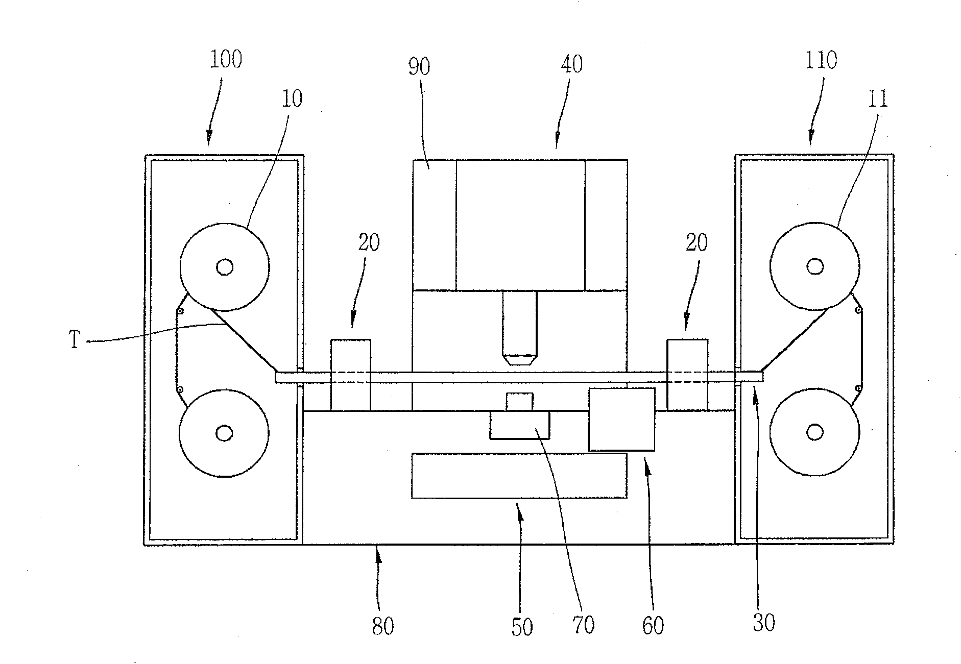
[0027] will refer to Figure 4 The chip supply unit loading device according to the present invention is explained.

[0028] Figure 4 is a perspective view showing a wafer supply unit of a die bonding apparatus to which the present invention is applied, and which has a die supply unit loading device according to the present invention.

[0029] The chip supply unit loading device is installed between the table 200 and the cassette unit 310 of the chip bonding device. The workbench 200 is provided at one side of the base 80, the cassette unit 300 includes a cassette 310, and the chip supply unit W1 can be loaded into the cassette.

[0030] The side wall of the cassette 310 of the tape cassette unit 300 is provided with a groove 311 with a certain length and depth, and the side of the chip supply unit W1 can be inserted i...


PUM


Abstract

An apparatus for loading a chip supplying unit is provided to prevent damage of the chip supplying unit by safely and quickly transferring the chip supplying unit loaded on a cassette unit. A transfer unit(500) is mounted on a frame, and a transfer guide(600) is reciprocated by the transfer unit. A clamping unit(700) is mounted on the transfer guide, and is reciprocated together with the transfer guide to load or unload a chip supplying unit(W) on or from a table. The transfer unit has a driving motor(510) mounted on the frame, an active pulley(520) engaged to a motor shaft of the driving motor, a passive pulley(530) mounted on the frame, and a belt(540) connecting the active pulley with the passive pulley.

Description

technical field [0001] The present invention relates to a chip supply unit loading device, in particular, the present invention relates to a chip supply unit loading device capable of quickly and smoothly transferring a chip supply unit loaded into a cassette to a workbench, and Quickly and smoothly reload the chip supply unit loaded on the table into the cassette. Background technique [0002] Generally, a liquid crystal display (LCD) device is provided with a plurality of driving circuits on its LCD panel. Each drive circuit is embodied as a drive IC (Integrated Circuit) chip and a plurality of connection terminals connected to the drive IC chip. [0003] will refer to figure 1 Explain the process of manufacturing the driver circuit. [0004] First, the leads of the driver IC chip 3 are respectively bonded to the metal pattern 2 of the tape T having the metal pattern 2 on the insulating film 1 by bonding means. The metal pattern 2 forms a plurality of connection termin...

Claims


Application Information

Patent Timeline
Patent Type & Authority Patents(China)
IPC IPC(8): H01L21/677H01L21/687H01L21/50
CPCE06B9/36E06B9/78
Inventor 李旻炯
Owner TOP ENG CO LTD
Why Eureka
Try Eureka