Method of constructing a thin film mirror

A thin-film mirror and structure technology, applied in instruments, installations, optics, etc., can solve the problems of inability to use and the geometric shape of the thin-film mirror is not accurate enough, and achieve the effect of low price and improved mirror price.

Inactive Publication Date: 2010-01-20
ROCKWELL COLLINS INC
View PDF4 Cites 2 Cited by
  • Summary
  • Abstract
  • Description
  • Claims
  • Application Information

AI Technical Summary

Problems solved by technology

In the border area, the geometry of the thin film mirror is not precise enough to be used, so in most cases this area has to be covered or blocked so that it cannot be seen

Method used


Image

  • Method of constructing a thin film mirror
  • Method of constructing a thin film mirror
  • Method of constructing a thin film mirror

Examples


Embodiment Construction

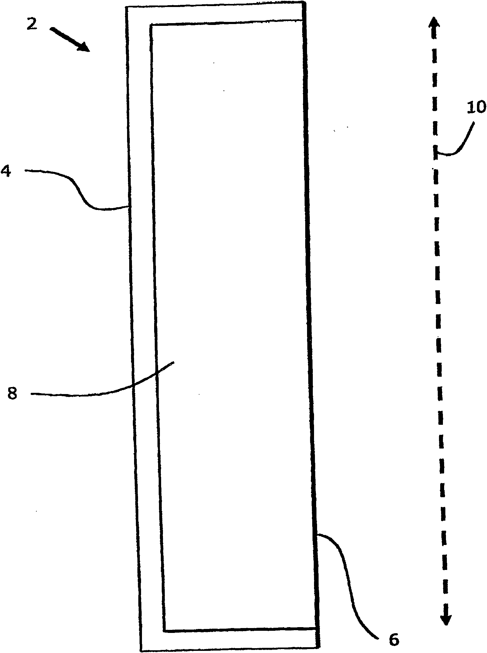
[0051] refer to figure 1 , the device 2 shown comprises a suction chamber 4 with a membrane mirror 6 attached to the edge of the suction chamber 4 . The air pressure in the interior 8 of the suction chamber 4 is not reduced. In other words, no partial vacuum is applied. The film 6 is thus not under tension and remains planar between the edges of the suction chamber 8 . The full usable width 10 of the suction chamber 8 is indicated by dashed lines.

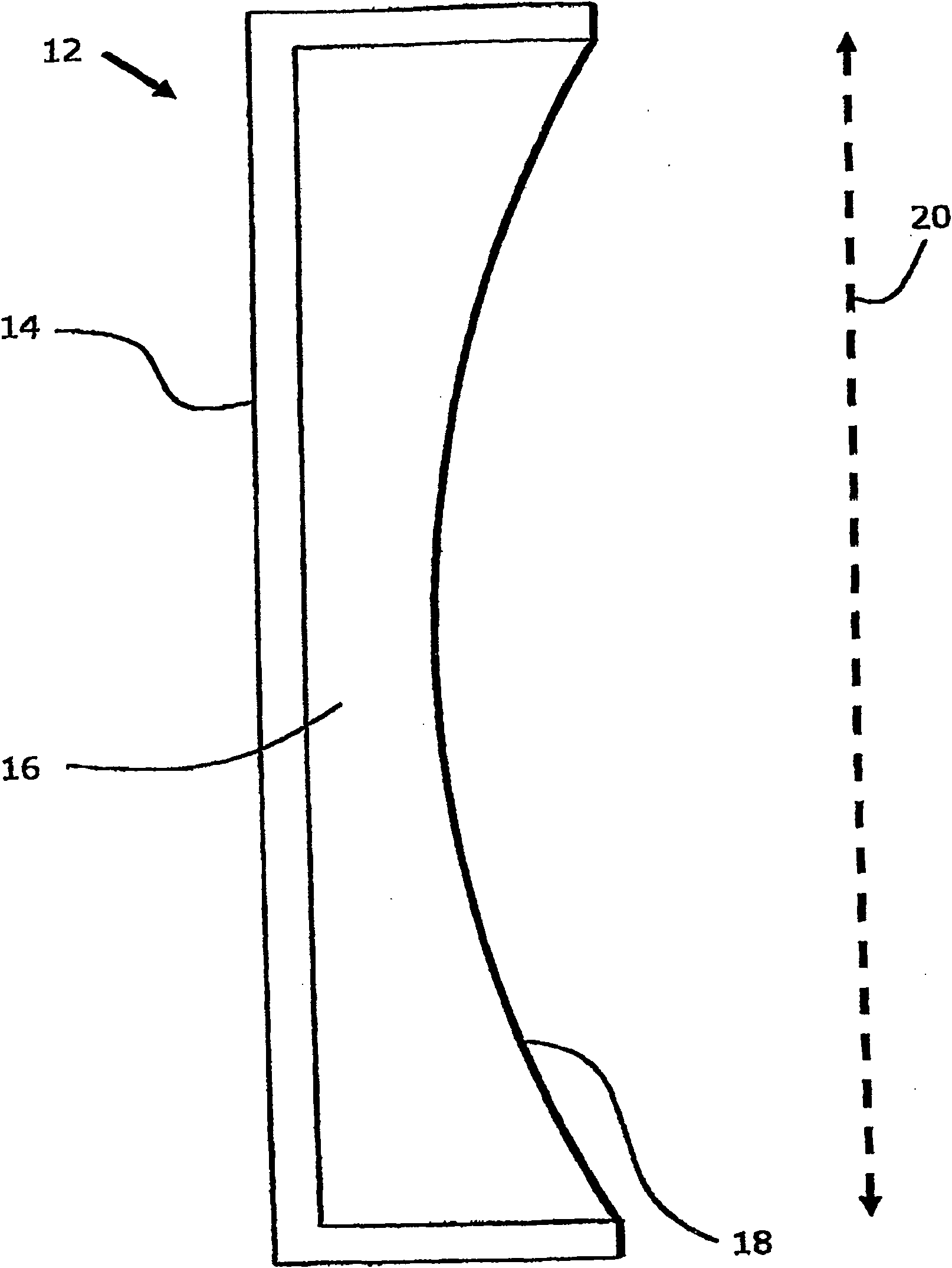
[0052] figure 2 Apparatus 12 including suction chamber 14 is shown. The interior 16 of the suction chamber 14 is already under partial vacuum. Thus, the film 18 has been drawn into the suction chamber 14 as shown. If the membrane 18 were under uniform tension, the shape formed by the membrane 18 in cross-section would be described as an arc of a circle. The radius of this circle will vary with the extent to which the film 18 is sucked into the suction chamber 14 . In this ideal case, the usable area of ​​the membrane 18 i...


PUM


Abstract

The present invention provides a method of constructing a thin film mirror, which method comprises: (i) attaching a thin film (72) to a suction chamber (68), the suction chamber (68) having edges which are for attaching the thin film (72) and which lie in a desired geometry for the thin film mirror to be constructed; (ii) applying a partial vacuum to the suction chamber (68) such that tension is introduced into the thin film (72); (Hi) adjusting the partial vacuum to form the thin film mirror but with the thin film mirror achieving the desired geometry only over a portion of the thin film mirror; (iv) providing first tensioning means (78, 80) and locally adjusting the first tensioning means (78, 80) such that the portion of the thin film mirror which achieves the desired geometry is increased, the first tensioning means (78, 80) being in contact with the surface of the thin film (72) adjacent to the edge of the suction chamber (68) at a first distance which is substantially uniform from the edge of the suction chamber (68); and providing second tensioning means (82, 84) and locally adjusting the second tensioning means (82, 84) such that the portion of the thin film mirror which achieves the desired geometry is further increased, the second tensioning means (82, 84) being in contact with the surface of the thin film (72) adjacent to the first tensioning means (78, 80) at a second distance which is substantially uniform from the edge of the suction chamber (68), and which second distance is greater than the first distance from the edge of the suction chamber (68) of the first tensioning means (78, 80).

Description

technical field [0001] The invention relates to a method of constructing a thin film mirror. Background technique [0002] Thin film mirrors are known. They are used to produce large field of view displays in image display devices. Graphic display devices provide displays for simulation, leisure, visualization or computer design. In displays for simulation, thin film mirrors are typically used as part of collimated or nearly collimated off-axis displays. Thin film mirrors are also used in other applications such as solar collectors and telescopes. [0003] Thin film mirrors utilize thin film structures. The film is typically a polymeric film, such as polyethylene terephthalate, or other suitable film. The film has a surface that has been aluminized to provide a reflective surface. [0004] The geometric accuracy of a thin-film mirror is the main factor determining the quality of the mirror and the practicality of the mirror. This is especially true in image display de...

Claims


Application Information

Patent Timeline
Patent Type & Authority Patents(China)
IPC IPC(8): G02B26/08G02B7/182
CPCG02B7/182G02B26/0825
Inventor R·E·克里克
Owner ROCKWELL COLLINS INC
Why Eureka
Try Eureka