Bi-directionally actuated thin membrane mirror

a thin-mold mirror, bi-directional technology, applied in mirrors, mountings, instruments, etc., can solve the problems of inability to meet the needs of laser beam applications, and relatively high cost of manufacture and assembly of actuators,

Inactive Publication Date: 2007-03-20
NORTHROP GRUMMAN SYST CORP
View PDF5 Cites 4 Cited by
  • Summary
  • Abstract
  • Description
  • Claims
  • Application Information

AI Technical Summary

Benefits of technology

[0008]The present invention resides in a thin membrane deformable mirror that is actuated bi-directionally and avoids the significant disadvantage of thin membrane mirrors. Briefly, and in general terms, the thin membrane deformable mirror of the present invention comprises a deformable membrane having a mirrored front face and a back face; a mirror frame for supporting the deformable membrane; and a set of independently controllable electrodes spaced from the back face of the membrane; at least one additional electrode spaced from the front face of the membrane. Finally, the mirror includes means for applying actuating electrical voltages to the set of electrodes, to deform the membrane to a desired surface profile needed to apply wavefront corrections to an optical beam impinging on the mirror, and to the at least one additional electrode, to compensate at least in part for any concave bias in the surface profile resulting from actuation of the set of electrodes.

Problems solved by technology

Although this arrangement simplifies control of the actuators, the gaps between mirror segments are unacceptable for most applications that use laser beams.
An overwhelming drawback to the use of independently controlled bi-directional actuators is the relatively high cost of manufacture and assembly of the actuators.
Unfortunately, however, the continuity of the thin membrane mirror gives rise to a significant, and sometimes critical, disadvantage.
The downward deformation of the entire membrane results in a concave and generally parabolic bias to the membrane.
This is usually not an acceptable solution, however, because the degree of the concave bias will vary with the current need for deforming the mirror to effect wavefront corrections.
One way to do this is to compensate for the bias with an adjustable rather than a fixed lens, but this obviously adds another layer of complexity to the mirror.

Method used


Image

  • Bi-directionally actuated thin membrane mirror
  • Bi-directionally actuated thin membrane mirror
  • Bi-directionally actuated thin membrane mirror

Examples


Embodiment Construction

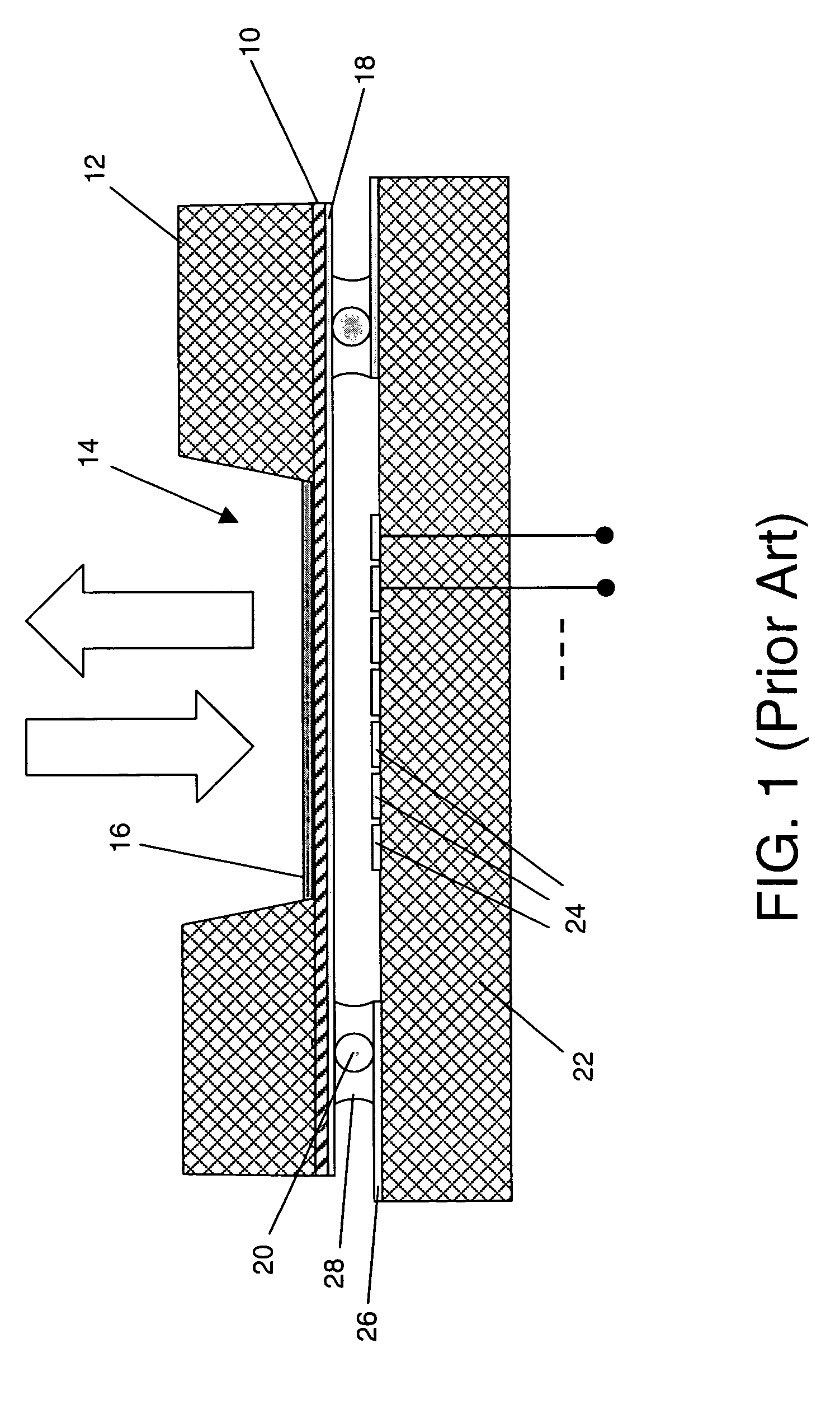
[0018]As shown in the drawings for purposes of illustration, the present invention pertains to thin membrane deformable mirrors. FIGS. 1–3 depict a typical thin membrane deformable mirror of the prior art, which will be discussed first.

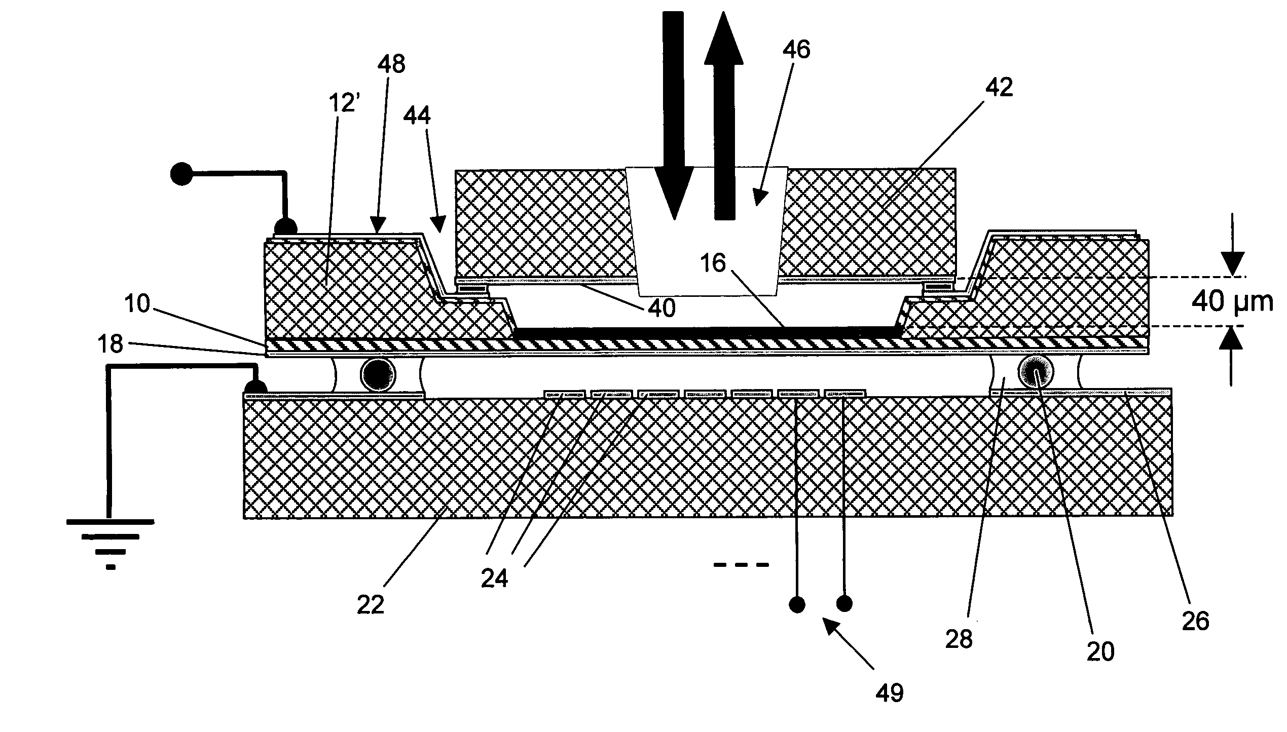
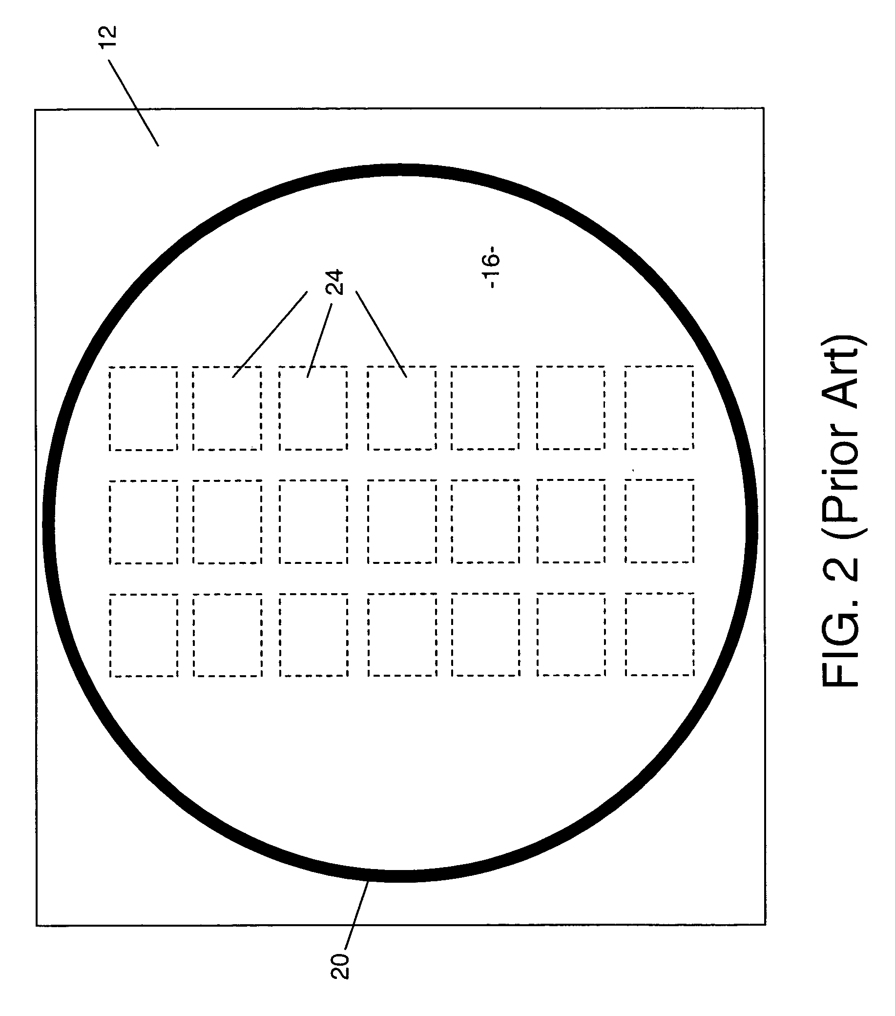
[0019]As best seen in FIG. 1, a typical thin membrane deformable mirror structure includes a mirror membrane, indicated by reference numeral 10, mounted in a mirror frame 12. By way of example, the membrane 10 may be of silicon nitride material, with a thickness of approximately 1 micron (1 μm) and the frame 12 is of silicon material of thickness approximately 0.5 mm. The frame 12 surrounds a mirror region 14, in which the membrane 10 has a reflective coating 16 formed over its upper or front face. The lower or back face of the membrane 10 is coated with an electrically conductive coating 18, using a material such as gold. A precisely dimensioned glass spacer bead 20 extends around the frame 12 and provides a desired uniform spacing between the conduc...


PUM


Abstract

A deformable membrane mirror and a related method for its use, the mirror including a deformable membrane having a reflective front face and a back face, and further including electrodes located on both sides of the membrane, to provide a desired surface contour without imparting a concave bias to the membrane. The electrodes include a first set of electrodes spaced from the back face of the membrane, and at least one additional electrode spaced from the front face of the membrane.

Description

BACKGROUND OF THE INVENTION[0001]This invention relates generally to deformable mirrors and, more particularly, mirrors of which the surface can be rapidly changed in contour. The deformable mirror is a key component in adaptive optics systems for various applications. For laser directed energy weapons, adaptive optics systems may be used to compensate for optical wavefront distortions caused by transmission of a laser beam through the atmosphere. Similarly, many large aperture telescopes employ adaptive optics to compensate for atmospheric turbulence. There are also a number of commercial products that employ adaptive optics to map imperfections in the human eye and provide a tool for adjusting vision correction procedures.[0002]All of these applications have in common the need to control the surface contour of a mirror in real time, i.e., rapidly enough to compensate for changes as they occur. A deformable mirror uses a matrix of individually controlled actuators, usually mounted ...

Claims


Application Information

Patent Timeline
Patent Type & Authority Patents(United States)
IPC IPC(8): G02B5/08G02B26/00
CPCG02B26/0825G02B26/06
Inventor HO, JAMES G.
Owner NORTHROP GRUMMAN SYST CORP
Why Eureka
Try Eureka