Thin film mirror

a thin film mirror and mirror technology, applied in the field of thin film mirrors, can solve the problems of difficult to obtain consistent flatness of the mirror reflecting surface, the relative weight of large glass mirrors is significant, and the thin glass mirror is likely to fractur

Inactive Publication Date: 2005-03-24
MARTINEZ SR EUGENE
View PDF1 Cites 3 Cited by
  • Summary
  • Abstract
  • Description
  • Claims
  • Application Information

AI Technical Summary

Benefits of technology

[0012] Among the several objects of the invention may be noted the provision of a novel thin-film mirror having a support frame with no gaps or steps at the corner film mounting surfaces where the thin film is adhered, a thin-film mirror having a support frame with no acute angles at the corner film mounting surfaces where the thin film is adhered, a thin-film mirror having a monocoque construction that eliminates gaps or steps at the corner film mounting surfaces where the thin film is adhered, a thin-film mirror having a one-piece support housing with no gaps or steps at the corner film mounting surfaces where the thin film is adhered, a thin-film mirror having a one-piece support housing with no acute angles at the corner film mounting surfaces where the thin film is adhered, a thin-film mirror that ...

Problems solved by technology

Relatively large glass mirrors have significant weight.
However thin glass mirrors are likely to fracture in drop tests that have become a standard requirement for TV manufacturers.
Consistent flatness of the mirror reflecting surface is also difficult to obtain with large thin glass mi...

Method used


Image

  • Thin film mirror
  • Thin film mirror
  • Thin film mirror

Examples


Embodiment Construction

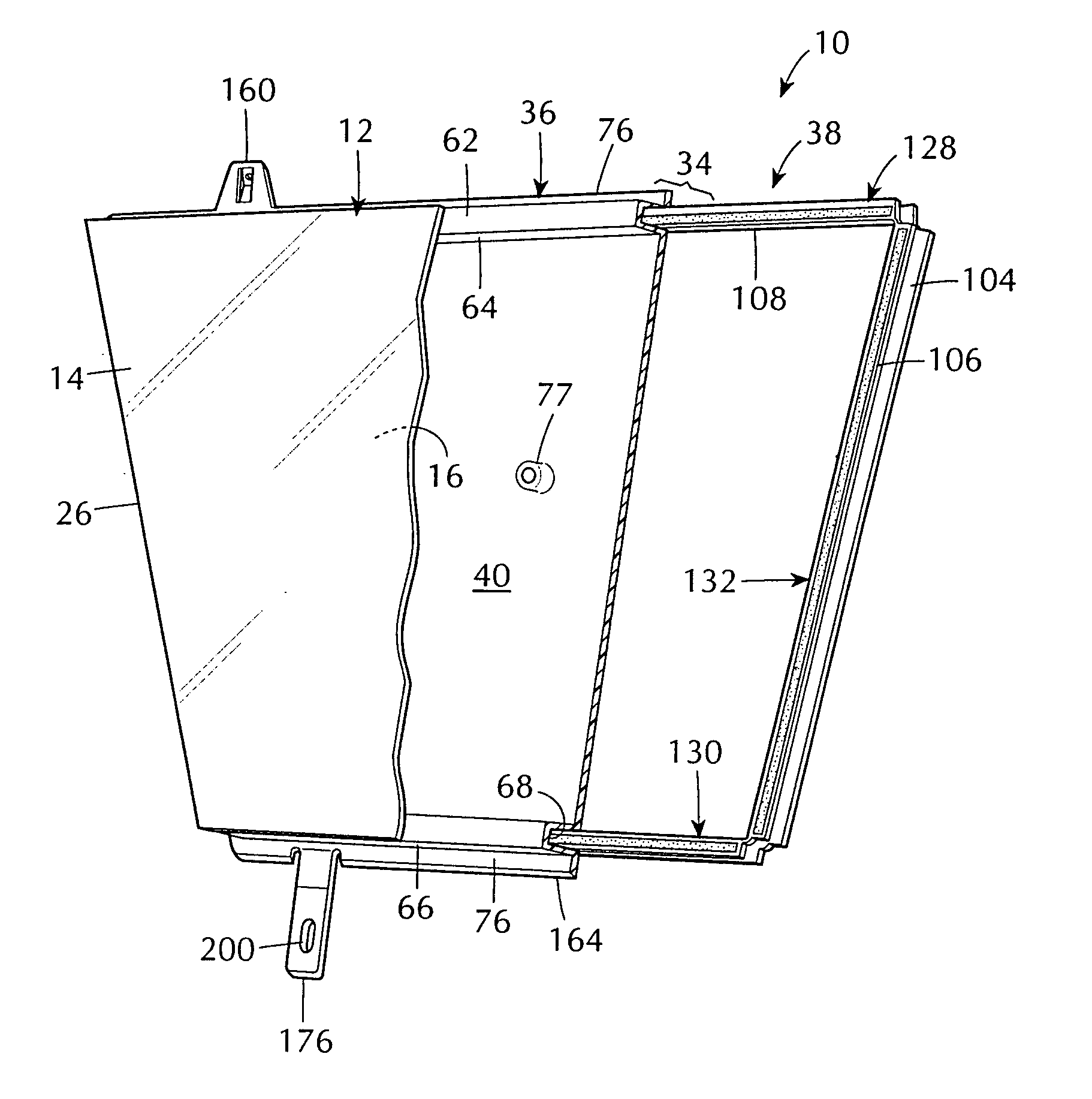
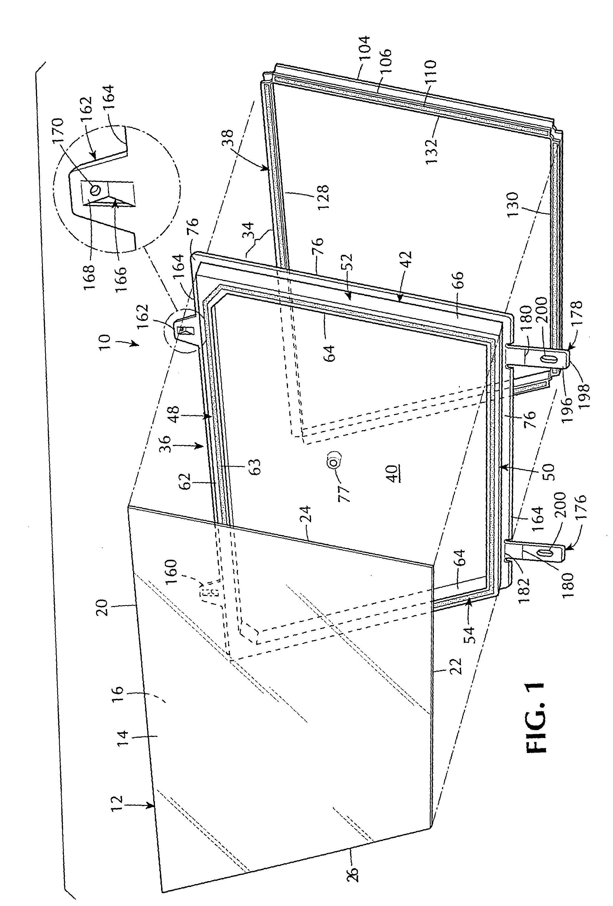
[0048] A thin-film mirror incorporating a preferred embodiment of the invention is generally indicated by the reference number 10 in FIG. 1.

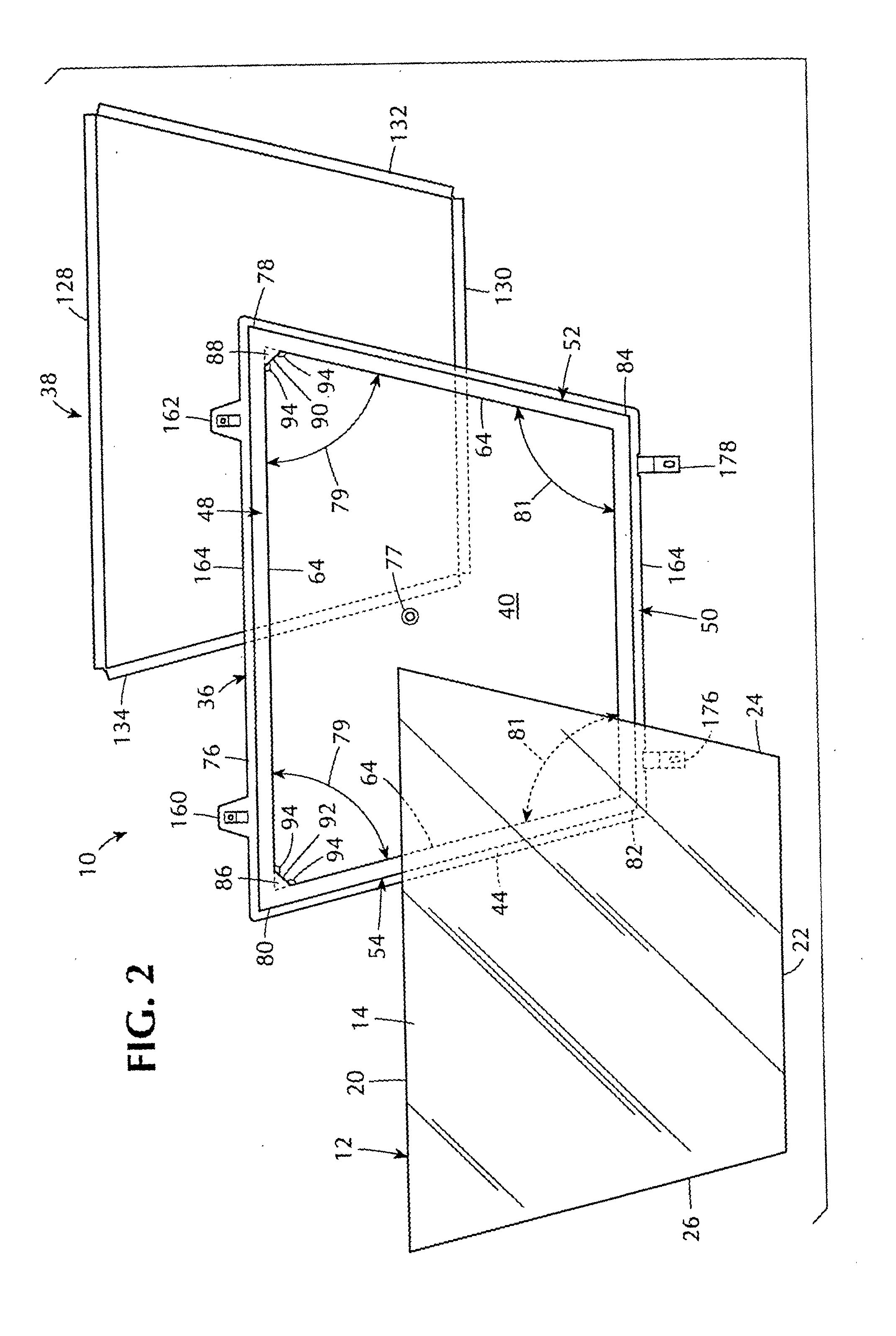
[0049] The thin-film mirror 10, also referred to as the mirror 10, includes a known thin reflecting film 12 (FIG. 1) with a reflecting surface 14 and a non-reflecting surface 16. The thin reflecting film 12 has the shape of a polygon, preferably a trapezoid, with parallel edge portions 20, 22 and inclined edge portions 24 and 26. The edge portions 20, 22, 24 and 26 of the reflecting film 12 are adhered at the non-reflective surface 16 to a support frame 34 (FIG. 3).

[0050] The support frame 34 (FIG. 3) includes a four-sided, miterless, one-piece molded housing 36 (FIGS. 1, 4 and 8) preferably formed of plastic and also referred to as the pan-shaped housing 36. The support frame 34 further includes a peripheral reinforcing member 38 (FIGS. 1, 8 and 13) for the pan-shaped housing 36. The pan-shaped housing 36 and the reinforcing member 38 have a ...


PUM


Abstract

The thin-film mirror includes a pan-shaped housing having a pan surface and a hollow wall bordering the pan surface. The hollow wall has a mounting surface for thin reflecting film, which mounting surface is stepped above the pan surface. The hollow wall has an open portion opposite the mounting surface and accommodates a reinforcing member that rigidities the pan-shaped housing. A thin reflecting film that spans the pan surface is secured to the film mounting surface. The pan-shaped housing is a miterless one-piece structure which can be in the form of a trapezoid. Hollow fillets can be provided at the acute angle corners of the trapezoid. The fillets constitute an additional mounting surface portion for the thin reflecting film and are formed such that no corner of the mounting surface has an acute angle.

Description

BACKGROUND OF THE INVENTION [0001] This invention relates to thin-film mirrors, and more particularly to a thin-film mirror having a novel support frame for supporting the thin reflecting film of the thin-film mirror, and a thin-film mirror with a novel monocoque construction. [0002] Mirrors are often used in optical systems to fold the optical path, such as the distance between a projector lens and a rear projection screen in a television (TV), in order to compact the size of the optical system and permit a corresponding reduction in cabinet size for the TV. Glass has long been used as the substrate for the reflective material of a mirror, which reflective material is generally a coating of aluminum or silver. The reflective material is usually applied to the front surface of the glass in an optical system to avoid having the projected light rays pass through the thickness of the glass. [0003] As the size of rear projection TV screens increase, the size of reflecting mirrors must a...

Claims


Application Information

Patent Timeline
IPC IPC(8): G02B7/182
CPCG02B7/182
Inventor MARTINEZ, EUGENE SR.
Owner MARTINEZ SR EUGENE
Why Eureka
Try Eureka