Method for testing gear wheels during their production in gear compound cutter

A technology for gear cutting machines and gears, which is applied to gear cutting machines, gear tooth manufacturing devices, manufacturing tools, etc., and can solve problems such as dimensional correction errors, affecting the production process, and measurement result errors

Inactive Publication Date: 2010-01-27
LIEBHERR VERZAHNTECHNIK GMBH
View PDF5 Cites 0 Cited by
  • Summary
  • Abstract
  • Description
  • Claims
  • Application Information

AI Technical Summary

Problems solved by technology

[0005] The aforementioned procedure creates the following problem: when measuring the distance across the ball in an air-conditioned measuring room specially installed for this purpose, the resulting measurement results cannot be imported back to affect the production process
If the gear is measured with a sensor or a stylus, the tool wear is not taken into account and after all the tool changes due to the tool wear process are not accurately determined either, resulting in errors in the measurement results and thus in the dimensional correction

Method used


Image

  • Method for testing gear wheels during their production in gear compound cutter

Examples


Embodiment Construction

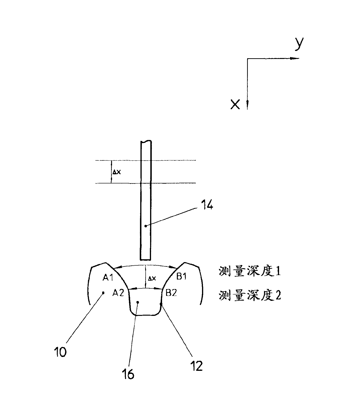
[0019] A part of the gear is indicated at 10, which has tooth flanks 12 in the form of involutes. The flanks 12 of the gear 10 are machined by means of a tool 14 such as a grinding wheel or a screw mill. Two measurement depths, measurement depth 1 and measurement depth 2 , are shown within tooth gap 16 . Due to the shape of the flank 12 , the distance between A1 and B1 at measuring depth 1 is greater than the distance between points A2 and B2 at measuring depth 2 . Since the distance to the gap center of the tooth gap 16 is known at each point of the involute, the radial depth-of-cut of the tool, Δx, at MD 1 and MD 2 is known. Δx corresponds to the center-to-center error of the tool 14 , which can be determined by means of a check measurement of the tooth flank distance and the resulting deviation from a predetermined target value.


PUM


Abstract

The invention relates to a method for testing gear wheels during their production in a gear cutting machine. According to said method, the tool is driven against the respective workpiece at specific points in order to determine potential deviations. Said deviations are then used to correct the setting of the tool by means of a control loop.

Description

technical field [0001] The invention relates to a method of inspecting gears during their manufacture in a gear cutting machine. Background technique [0002] In addition to numerous inspection standards, the determination of the ball distance is one of the most important criteria, because the produced gear can be determined to be qualified or unqualified through the ball distance. For reliable production, the inspection of the cross-ball pitch and optionally the machine correction associated therewith is absolutely necessary. The determination of the over-ball distance is standardized by DIN 3960. It is the diameter test dimension for tooth thickness. [0003] Randomly check the pitch of the gears during production. If the inspection level is increased, ie if the number of workpieces to be inspected is increased, the metrology and time required and the costs associated therewith also increase. A number of measuring systems can usually be used to determine the distance a...

Claims


Application Information

Patent Timeline
Patent Type & Authority Patents(China)
IPC IPC(8): G01B5/20
CPCG01B21/20B23F23/1218
Inventor 克劳斯·芬肯维尔特安德烈亚什·梅尔
Owner LIEBHERR VERZAHNTECHNIK GMBH
Why Eureka
Try Eureka