Fuse supporter for power

A technology of fuses and supporters, which is applied in the direction of circuits, electrical components, emergency protection devices, etc., and can solve problems such as deformation or penetration, damage to power fuses 3, and unstable power supply

Inactive Publication Date: 2012-07-25
DAIHEN CORP
View PDF1 Cites 0 Cited by
  • Summary
  • Abstract
  • Description
  • Claims
  • Application Information

AI Technical Summary

Problems solved by technology

However, if the size or material of the first and second movable side electrodes 203a' and 203b' is wrongly selected, a large amount of manpower is required to bend the first and second movable side electrodes, so the installation operation is complicated and dangerous. question
[0008] Therefore, in order to solve the above-mentioned problem, the size or material of the first and second movable side electrodes 203a' and 203b' can be selected without requiring a lot of manpower to bend the loop coil. Power fuse control body 2 'Installed on the fuse housing body 1 ’, the extent to which the first and second movable side electrodes are embedded in the first and second fixed side electrodes 102a’, 102b’ becomes smaller, so there is a power fuse holding body 2 'Easily accommodates the main body from the fuse 1 'Pull out problem
[0009] In addition, when the electric fuse 3 is attached to the electric fuse holding body 2', in order to fix the electrode 3a of the electric fuse 3 with the front end of the screw 10, the surface of the electrode 3a is scratched, so there is a possibility that the electric fuse 3 may be damaged due to corrosion or plating peeling off. The problem of unstable power supply
In addition, since the electrode 3a is formed with a cavity by the stamping, the strength becomes relatively low, so there is a problem that the electrode 3a in contact with the tip of the screw 10 may be deformed or penetrated due to the concentration of fastening stress, and the power fuse 3 may be damaged.

Method used


Image

  • Fuse supporter for power
  • Fuse supporter for power
  • Fuse supporter for power

Examples


Embodiment Construction

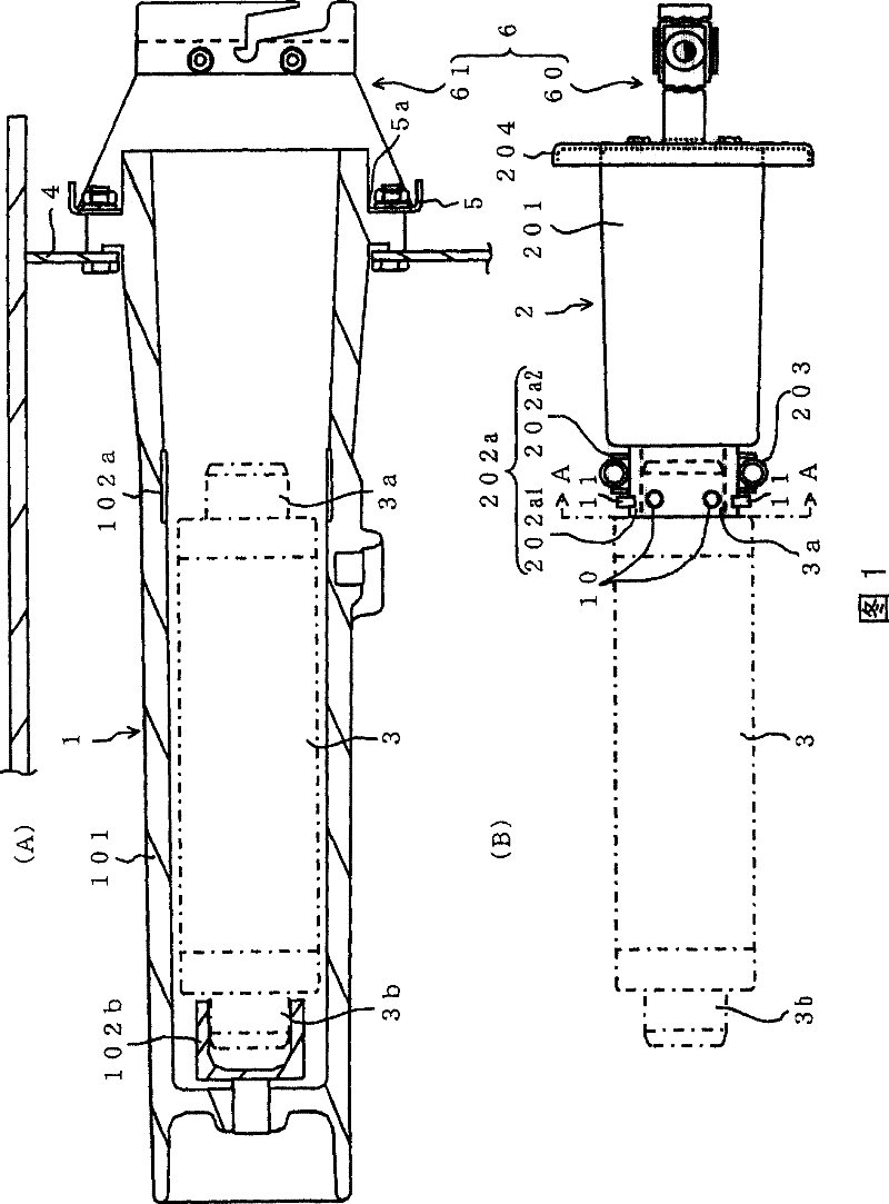
[0062] figure 1 (A) is a longitudinal sectional view showing an embodiment of the fuse housing body constituting the electric fuse holder according to the present invention, and (B) is a longitudinal sectional view showing an electric fuse holding body constituting the electric fuse holder according to the present invention A side view of an embodiment of .

[0063] As shown in the figure, the power fuse housing body 1 is composed of an insulating cylindrical member 101 having a bottom and first and second fixed-side electrodes 102a, 102b, and is completely housed along the longitudinal direction of the cylindrical member 101. For example, a ring-shaped first fixed-side electrode 102a is attached to the inner peripheral surface of the power fuse 3 at a position facing the first (opening side of the cylindrical member 101) electrode 3a. In the state of being completely accommodated along the longitudinal direction of the cylindrical member 101, the inner peripheral surface of...


PUM


Abstract

A fuse supporter for electricity use includes: electric fuse housing body (1) on internal surrounding face of whose cylinder part (101) fixed side electrodes (102a, 102b) are arranged; and fuse holding body (2) which is formed for holding an electrode of the fuse at an end of a joint part (201) and which is equipped with electrode holding part (202a) which is winded by movable side electrode (203) over all internal surrounding direction of the fixed side electrode (102a) and contacts with the same, and cover part (204) is arranged at another end of the joint part. Further includes rotatary / linear moving mechanism (6) for fuse holding body which artificially applies rotating force on the fuse holding body inserting into the fuse housing body thereby to linearly move the fuse holding body as well as rotate the same. In this manner, manpower applied on electric fuse holding body is reduced as the fuse holding body is mounted on the electric fuse housing body.

Description

technical field [0001] The present invention relates to a fuse holder (holder) for electric power, which includes a power fuse accommodating body and a power fuse holding body, and the power fuse holding body is accommodated in the power fuse accommodating body. Background technique [0002] In order to protect a transformer from a short-circuit current caused by an overload current or a short-circuit accident on the load side, a power fuse is usually connected to the power supply side of the power transformer. The power fuse is housed in the power fuse holder and attached in a state of penetrating through the case of the power transformer. [0003] Figure 10 (A) is a longitudinal sectional view of a power fuse housing body constituting a conventional power fuse holder, and (B) is a side view of a power fuse holding body constituting the power fuse holder. [0004] The fuse holder for electric power is composed of a fuse holding body 1' and a power fuse holding body 2'. T...

Claims


Application Information

Patent Timeline
Patent Type & Authority Patents(China)
IPC IPC(8): H01H85/22
Inventor 绫部浩一秋山知一马场昭
Owner DAIHEN CORP
Why Eureka
Try Eureka