Air cushion cylinder having a sealer of air sealing and locking device and the method for preparing the same
What is AI technical title?
AI technical title is built by PatSnap AI team. It summarizes the technical point description of the patent document.
A technology of sealing body and buffer body, applied in envelope/bag manufacturing machinery, packaging, transportation and packaging, etc., can solve problems such as damage, low practicability of air buffer body, and inability of air to enter automatically.
Active Publication Date: 2007-09-19
KUNSHAN AIRBAG PACKING CORP
View PDF3 Cites 71 Cited by
Summary
Abstract
Description
Claims
Application Information
AI Technical Summary
This helps you quickly interpret patents by identifying the three key elements:
Problems solved by technology
Method used
Benefits of technology
Problems solved by technology
Generally, there are two types of air buffers. One is composed of independent air columns. Each air column has an independent air inlet. When inflating, each air inlet must be inflated, so it is time-consuming and uneconomical to inflate. In addition, the new type in Taiwan, China In Patent No. M255242, a plurality of heat-resistant prints are sandwiched between the upper and lower air valve membranes as air nozzles for inflating air intake. Unfortunately, the inflating channel cannot be inflated at one time to automatically open the air inlets of each sealing body.
The other type consists of one or two inflation ports with non-independent air columns. The disadvantage is that if one is damaged, all the air columns will be degassed together, such as US Patent No. 5427830
In addition, these two types of air buffers only raise the inner membrane to increase the air pressure, but do not further study the method of further locking the air. Therefore, the air in the air column after inflation cannot last for a long time without leaking. The above shortcomings make the practicability of the air buffer lower.
[0003] China Taiwan Invention Patent No. 92113574 approved on May 20, 2003 discloses an installation structure for a switch valve of a sealed body, wherein the switch for air entering the sealed body uses two pieces of inner film and one side of the outer film to form a switch The passage of the valve, when inflated, the sealing body expands to block the passage. The patent only describes how to block the air in the sealing body from leaking out, but does not explain how to simplify the inflation. By design, air cannot automatically enter the seal
Method used
Image
Click on the blue label to locate the original text in one second.
Reading with bidirectional positioning of images and text.
Examples
no. 1 example
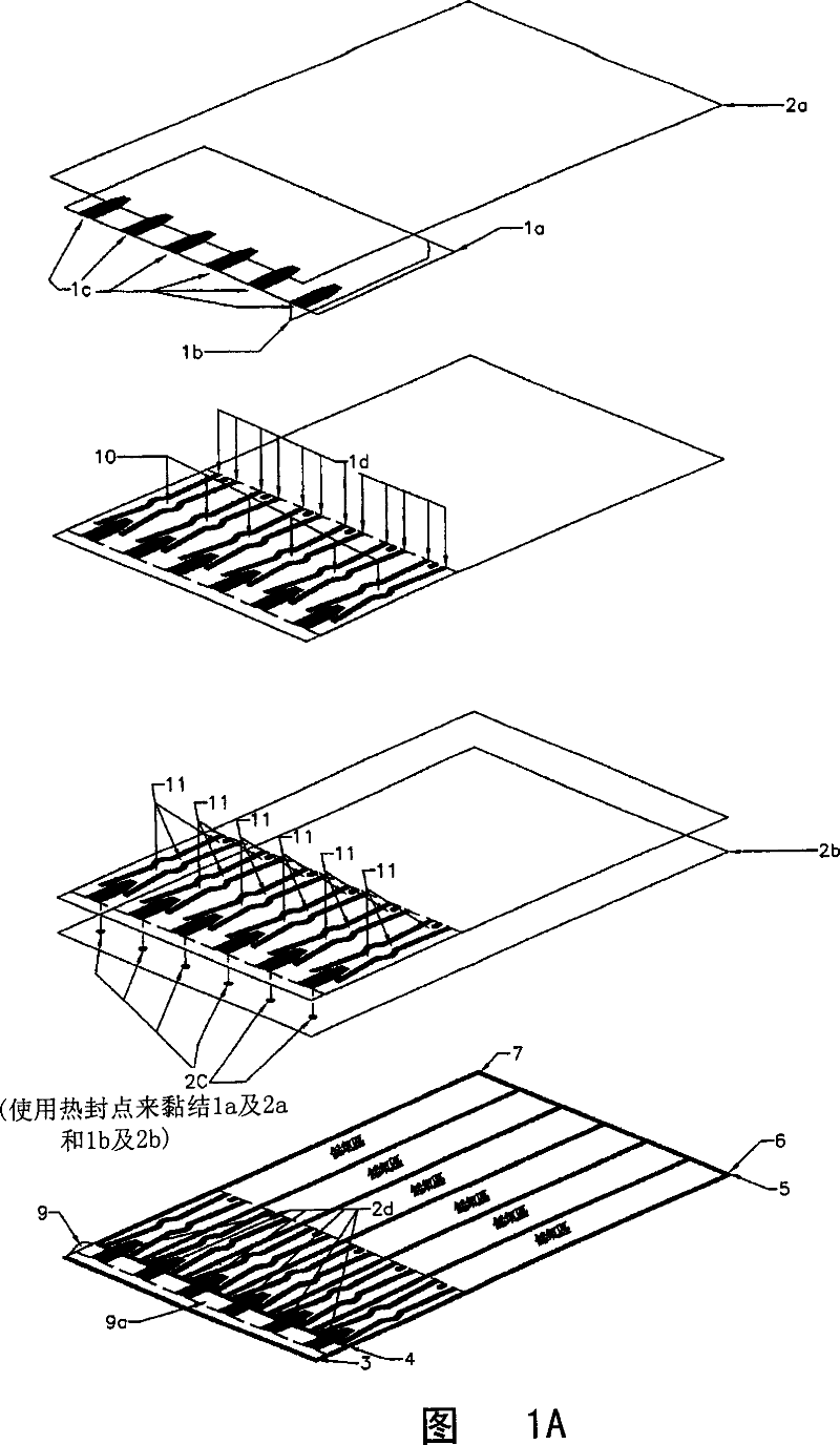
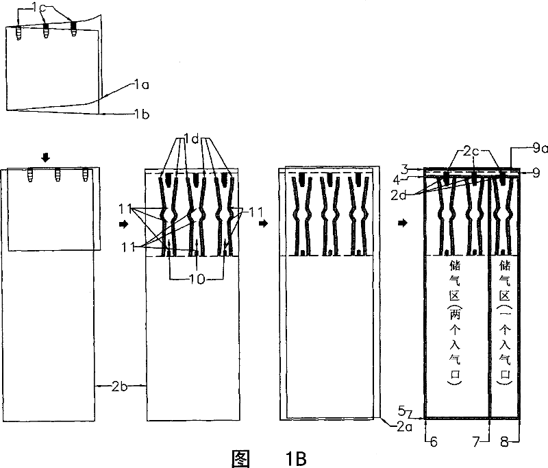
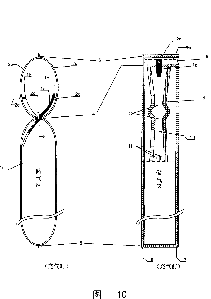
[0015] Please refer to FIG. 1A to FIG. 1C , which show the first embodiment of the air buffer body of the present invention, and the inner membrane adheres to the wall.
Embodiment approach
[0016] The air-filled buffer body includes: two inner membranes 1a and 1b interposed between two outer membranes 2a and 2b. The heat-resistant material 1c is formed between the two inner films 1a and 1b. The implementation is as follows:
[0017] First fold the inner membrane 1a, 1b and the outer membrane 2b, and apply heat seal 1d along the bottom of the heat-resistant joint 1c to form the air path 10, and set the bottleneck that is easy to plug, that is, the easy-to-plug section 11; and then combine with the outer membrane 2a Folding, applying heat-sealing lines 3, 4., 5, 6, 7, 8 to divide the sealing body into two areas, one is the inflatable channel area 3-4, and the other is the gas storage area 4-5, 6, 7 , 8 are heat-sealing edges, make these two districts be bounded by heat-sealing line 4, butt up and down. Due to the heat-resistant properties of the heat-resistant glue 1c in the air-filled channel area, the inner films 1a and 1b are not bonded after being heat-sealed...
no. 2 example
[0039] The second embodiment of the manufacturing method of the air buffer body with the sealing body automatic air-tightening and air-locking device of the present invention, the inner membrane includes the following steps:
[0040] Step 1: Provision of the second inner membrane.
[0041] Step 2: Apply heat-resistant glue on the top of the inner film 1a facing 1b at equal distances, and then heat-seal the air travel path and the preset easy-to-plug section of the two inner films.
[0042] Step 3: The two inner membranes are placed in the middle of the two outer membranes without attaching either side of the outer membranes.
[0043] Step 4: Apply heat-sealing point 2c to the apex of several heat-resistant joints 1c on the outer film.
[0044] Step 5: Apply a heat-sealed horizontal line 4. At the isosceles of the heat-resistant joint of the outer membrane, distinguish the air channel and the gas storage area. Give heat-sealing horizontal line 3,5 again.
[0045] Step 6: App...
PUM
Abstract
The invention relates to an air buffer having an automatic seal body air shutting-off and locking device and a making method thereof. The air buffer comprises a seal body composed of a continuous film coil and comprising two pieces of external film and two pieces of internal film, a plurality of equidistant heat-resistant nodes made from heat-resistant material are coated on the top of the internal surface of one internal film, and hot seal nodes are arranged at the positions at the same height as the heat-resistant nodes of one external film, and hot seal transversal lines are employed to divide the seal body into aerating channel regions and air storing columns, the aerating channels join the air storing columns through the hot seal lines, an internal film with heat-resistant nodes is arranged on the external film to make the internal film and the external film unjoined to form a sole channel air inlet. When aerating, the air channel portions of the two pieces of external films will expand to draw the internal films joined therewith, thus to allow all the air inlets along the air channels to open indirectly. In this way, a plurality of seal bodies are needed to be aerated, the air inlets are shut off and the air inlet paths are locked after aerating, thereby the air buffer having dual air shutting-off functions and durable seal performance.
Description
technical field [0001] The present invention relates to an air cushioning device for inner packaging, in particular to an air cushioning body with a device for automatically closing and locking air in a sealing body and a manufacturing method thereof. Background technique [0002] It is a trend to heat-seal the resin film as the base material to form a sealed body, and use it as the cushioning material of the inner packaging after inflation. Generally, there are two types of air buffers. One is composed of independent air columns. Each air column has an independent air inlet. When inflating, each air inlet must be inflated, so it is time-consuming and uneconomical to inflate. In addition, the new type in Taiwan, China In the patent No. M255242, a plurality of heat-resistant prints are sandwiched between the upper and lower air valve membranes as the air nozzles for inflating air. Unfortunately, the inflating channels cannot automatically open the air inlets of each sealing b...
Claims
Application Information
Patent Timeline
Application Date:The date an application was filed.
Publication Date:The date a patent or application was officially published.
First Publication Date:The earliest publication date of a patent with the same application number.
Issue Date:Publication date of the patent grant document.
PCT Entry Date:The Entry date of PCT National Phase.
Estimated Expiry Date:The statutory expiry date of a patent right according to the Patent Law, and it is the longest term of protection that the patent right can achieve without the termination of the patent right due to other reasons(Term extension factor has been taken into account ).
Invalid Date:Actual expiry date is based on effective date or publication date of legal transaction data of invalid patent.

