Compensation method, compensated regulator and electronic circuit

一种电子电路、补偿方法的技术,应用在调节电变量、控制/调节系统、仪器等方向,能够解决过度补偿、不同Idr1和Idr2电流等问题

Inactive Publication Date: 2007-09-19
SHENZHEN STS MICROELECTRONICS CO LTD
View PDF0 Cites 13 Cited by
  • Summary
  • Abstract
  • Description
  • Claims
  • Application Information

AI Technical Summary

Problems solved by technology

[0014] The problem with the low dropout regulator 100 shown in Figure 1 is that different load currents cause different Idr1 and Idr2 currents
Therefore, if Z1 = P2 at light loads, the regulator 100 tends to overcompensate at heavy loads

Method used


Image

  • Compensation method, compensated regulator and electronic circuit
  • Compensation method, compensated regulator and electronic circuit
  • Compensation method, compensated regulator and electronic circuit

Examples


Embodiment Construction

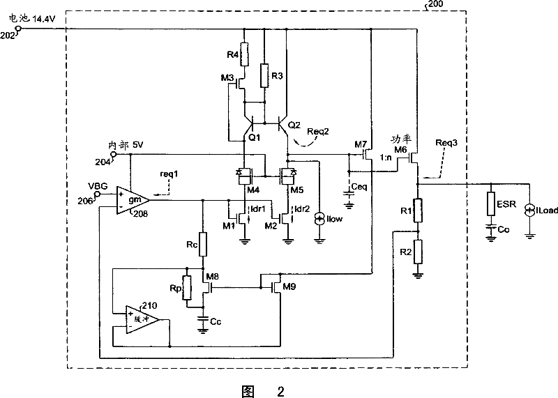
[0028] In accordance with the present invention, the above-described compensation method and circuit 200 shown in FIG. 2 forces the zero point Z1 and the pole P2 to have substantially the same dependence on the load current (noad).

[0029] Referring to Figure 2, the internal zero point Z1 is defined as:

[0030] Z1=Rzero×Cc=(Rc+(Rp‖R onM8 ))×Cc………………(1)

[0031] The area ratio of transistors M6 and M7 is n:1, and the area ratio of transistors M8 and M9 is 1:1. In low quiescent current (Iq) regulators, resistors R1 and R2 are very large, so I ds_M6 ≈Iload. Buffer 210 is used to force V gs_M8 =V gs_M9 . Transistor M8 generally operates in the above-mentioned triode region, and transistor M9 generally operates in the saturation region, thus:

[0032] R onM 8 = 1 g m 9 = 1 ...


PUM


Abstract

The invention relates to a compensation regulator, including: transconductance stage, with the positive input terminal, negative input terminal, and output terminal for receiving the reference voltage; adjust the compensation block, coupled to the place between the output terminal and earth of this transconductance stage; feedback circuit, with the first node for coupling to this compensation regulator output terminal, the second node for coupling to the negative input terminal of this transconductance stage and the third node for coupling to ground; drive stage, with the input terminal for coupling to the output terminal of this transconductance stage, the current output terminal for coupling to the output terminal of this compensation regulator, and sensing output terminal for coupling to this adjustable compensation block.

Description

technical field [0001] The present invention relates to linear regulator circuits and, more particularly, to linear regulator circuits with stable compensation circuits and methods that are useful when used in automotive applications. Background technique [0002] A conventional regulator integrated circuit 100 used in an automotive application is shown in FIG. 1 . In a typical embodiment, transistors M1 and M2 are 5V NMOS devices, transistors M4 and M5 are HV-NDMOS devices, and transistors M3 and M6 are HV-PMOS devices. Transistors Q1 and Q2 are bipolar transistors. An external 14.4V battery voltage is applied at node 102 , an internal 5V battery voltage is applied at node 104 , and a bandgap voltage VBG is applied at node 106 . An operational amplifier or gm stage 108 is used in this feedback loop. As shown, the output of the regulator 100 drives the output load. [0003] In the above regulator loop of the circuit shown in Figure 1, there are three poles and two zeros,...

Claims


Application Information

Patent Timeline
Patent Type & Authority Applications(China)
IPC IPC(8): G05F1/56
CPCG05F1/575
Inventor 林大松闸钢
Owner SHENZHEN STS MICROELECTRONICS CO LTD
Why Eureka
Try Eureka