Power supply device, led driver, illumination device, and display device

A technology of LED driver and power supply device, applied in the field of LED backlight system, which can solve the problems of no suggestion or mention of circuit scale and efficiency, different configurations, no description of boost circuit, etc.

Inactive Publication Date: 2007-10-31
ROHM CO LTD
View PDF2 Cites 22 Cited by
  • Summary
  • Abstract
  • Description
  • Claims
  • Application Information

AI Technical Summary

Problems solved by technology

However, this document does not describe that the booster circuit is a charge pump, so naturally there is no suggestion or reference to the above-mentioned problems (larger circuit size and reduced efficiency) that accompany when trying to realize the state control of the charge pump and these problems s solution
[0013] The conventional technique of Patent Document 2 uses a current mirror instead of a charge pump to generate a driving voltage for an LED, and thus is fundamentally different from the configuration of the present invention

Method used


Image

  • Power supply device, led driver, illumination device, and display device
  • Power supply device, led driver, illumination device, and display device
  • Power supply device, led driver, illumination device, and display device

Examples


Embodiment Construction

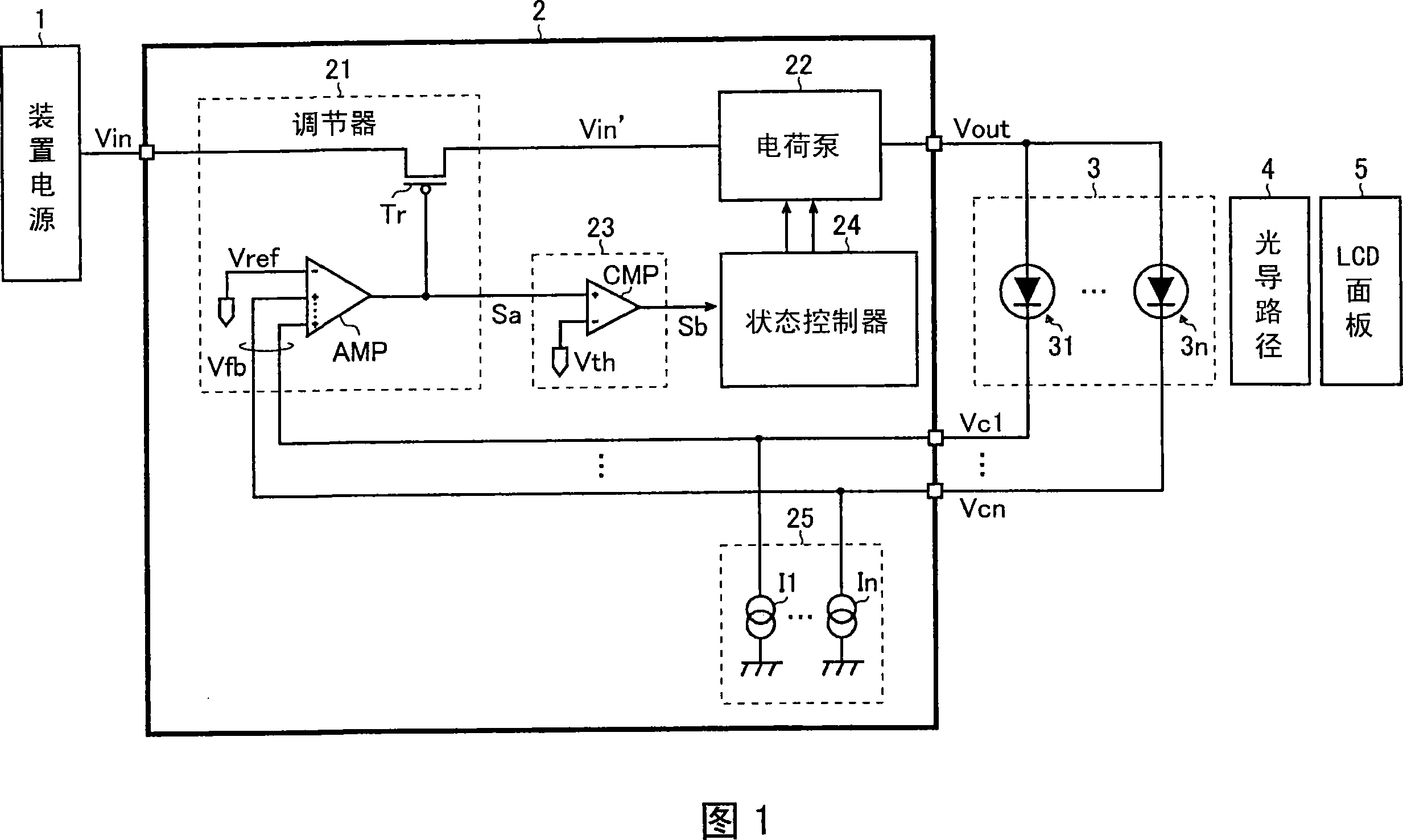
[0020] FIG. 1 is a block diagram showing an embodiment of a display device according to the present invention. As shown in this figure, the display device of this embodiment is a transmissive liquid crystal display including a device power supply 1, an LED driving device IC 2, a light emitting part 3, a light guiding path 4, and a liquid crystal display panel 5 (hereinafter referred to as "LCD (liquid crystal display) display) panel 5").

[0021] The device power supply 1 supplies power to the LED driver 2 and other components in the display device, which may be an AC / DC converter generating DC (direct current) voltage from commercial AC (alternating current) voltage, or a battery such as a rechargeable battery .

[0022] The LED driving device IC 2 powered by the input voltage Vin from the device power supply 1 drives and controls the LEDs 31 to 3 n forming the light emitting section 3 . The configuration and operation of the LED driver IC will be described in detail below....


PUM


Abstract

A power supply device has a regulator that performs conductivity control of an output transistor in such a way that a feedback voltage according to an output voltage is made equal to a reference voltage; a charge pump that produces the output voltage by stepping up an input voltage from the regulator; a detector that detects whether or not a control voltage of the output transistor has reached a threshold voltage; and a state controller that changes a step-up factor of the charge pump based on a comparison result of the detector. With this configuration, despite having a small-scale circuit configuration, the power supply device can appropriately perform state control of the charge pump.

Description

technical field [0001] The present invention relates to a power supply device that generates a desired output voltage from an input voltage, and to an LED (Light Emitting Diode) drive device, a lighting device, and a display device incorporating the power supply device. For example, the present invention relates to an LED backlight system for a liquid crystal display. Background technique [0002] FIG. 3 is a block diagram showing an example of a conventional LED driving device. [0003] As shown in this figure, a conventional LED driving device generally used is configured as follows. In order to obtain the desired output voltage Vout from the input voltage Vin, the regulator 101 generates the input voltage Vin' to be input to the charge pump 102 from the input voltage Vin, wherein the output voltage Vout is fed back to this regulator 101, and the first to The nth detectors 103-1 to 103-n individually detect the ratio between the input voltage Vin and the output voltage V...

Claims


Application Information

Patent Timeline
Patent Type & Authority Applications(China)
IPC IPC(8): H02M3/00G09G3/36G09G3/22
CPCH05B33/0827Y02B20/346H05B33/0815G02F2001/133612G02F1/133612H05B45/38H05B45/46Y02B20/30
Inventor 中尾重治大宫裕司
Owner ROHM CO LTD
Why Eureka
Try Eureka