Device for contactless determination of rotation and/or position of an object having an encoder

An encoder and generator technology, applied in the field of speed and/or position devices, which can solve problems such as unsatisfactory symmetry characteristics

Active Publication Date: 2008-01-02
CARL FREUDENBERG KG
View PDF2 Cites 8 Cited by
  • Summary
  • Abstract
  • Description
  • Claims
  • Application Information

AI Technical Summary

Problems solved by technology

The symmetry properties achievable by the device are unsatisfactory

Method used


Image

  • Device for contactless determination of rotation and/or position of an object having an encoder
  • Device for contactless determination of rotation and/or position of an object having an encoder
  • Device for contactless determination of rotation and/or position of an object having an encoder

Examples


Embodiment Construction

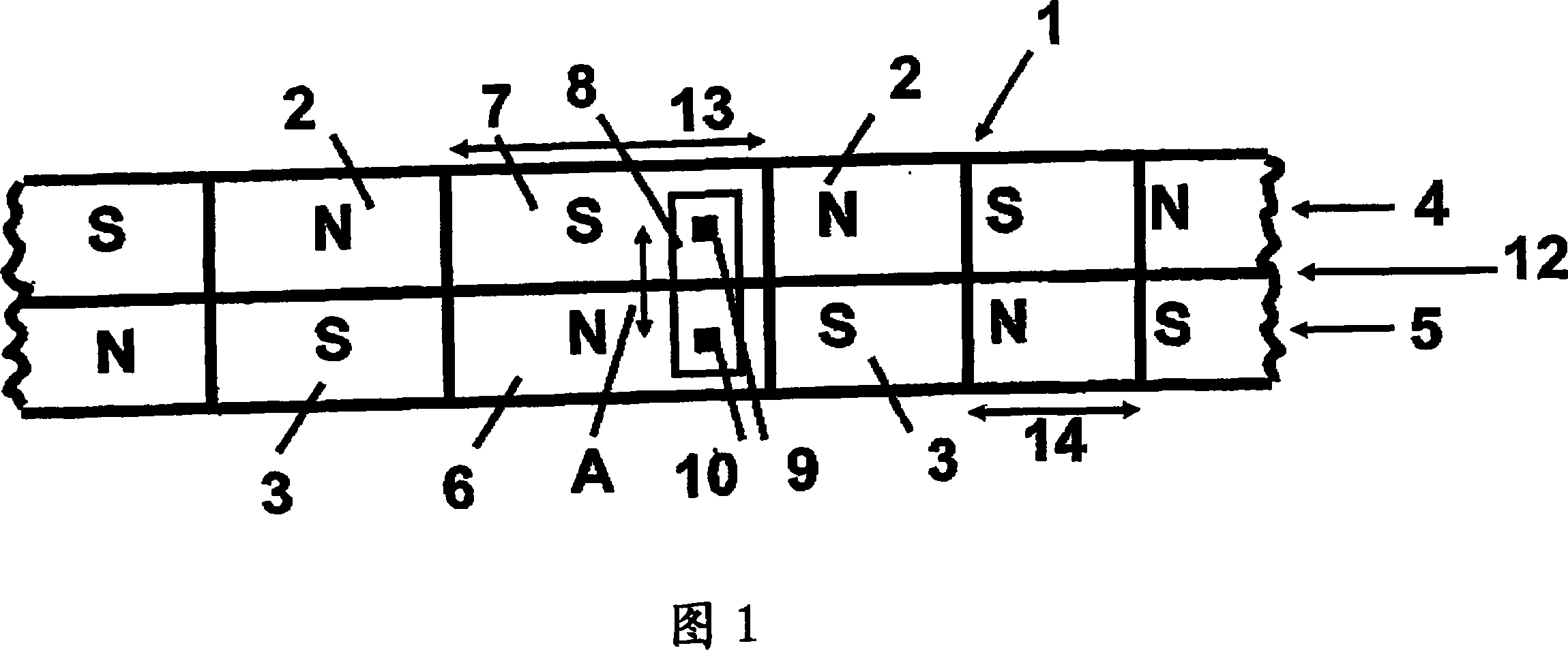
[0013] The various parts of the device are not shown in the figure, because these parts are known per se and can also be known from the aforementioned US publications belonging to the prior art. Therefore, FIG. 1 shows a part of the surface of an encoder designed as a dual-track encoder (Doppelspurencoder) 1, and the encoder is magnetized oppositely with regular N poles 2 and S poles 3. A corresponding number of poles 2 and 3 are arranged on each encoder track 4 and 5. The number of poles 2 and 3 is determined by a predetermined indexing angle, which is usually between 3° and 12° for regular poles 2 and 3. For each regular pole 2 and 3, the pole width or angular length 14 is the same size. In addition to the regular poles 2 and 3, irregular poles 6 and 7 with a larger angular length 13 (pole width) are arranged on each of the encoder tracks 4 and 5, which are also opposite to each other Geomagnetization. The dual-track encoder 1 is equipped with a differential Hall sensor 8 and is...


PUM


Abstract

The present invention relates to a device which is used for measuring the rotary speed and / or position of the generator component which can rotate around the axial cord without contact, the device is provided with a circular permanent-magnet encoder which includes a N pole and a S pole which are alternately arranged in the circumference direction and at least two different pole width, the encoder is provided with a scanning head with difference hall transducer, wherein, the encoder is designed to be a double rail encoder (1) with inverse magnetizations; and each sensor element (9, 10) of the difference hall transducer (8) is arranged to one of the encoder rails (4, 5).

Description

Technical field [0001] The present invention relates to a device for non-contact detection of the rotational speed and / or position of a generator part (Geberteil) that can rotate about an axis. The device has a ring-shaped permanent magnet encoder with a circumferential direction Regular N poles and S poles and at least one irregular pole are alternately arranged, and the encoder also has a scanning head with a differential Hall sensor. Background technique [0002] This type of device is used in many aspects to detect the speed of the shaft and also to measure the position of the shaft. The encoder is installed on the generator part and the scan head provides corresponding signals, from which the speed information or position information can be derived. [0003] A device is known from US 2003 / 01 16703 A1 in which an encoder is equipped with alternating regular N poles and S poles, and the device is provided with a scanning head with a differential Hall sensor. In order to allow ...

Claims


Application Information

Patent Timeline
Patent Type & Authority Applications(China)
IPC IPC(8): G01P3/481G01D5/245
CPCG01P3/487F02D41/0097G01D5/2457F02D41/009G01D5/145
Inventor C·冈德R·海因里希M·冯盖绍H·穆特尔L·萨拉尼亚克R·莱茵斯
Owner CARL FREUDENBERG KG
Why Eureka
Try Eureka