Visible light and ir combined image camera with a laser pointer

A camera and visible light technology, applied in image communication, instruments, scientific instruments, etc., can solve problems such as difficult and accurate identification, and achieve low-cost effects

Active Publication Date: 2008-01-23
JOHN FLUKE MFG CO INC
View PDF1 Cites 67 Cited by
  • Summary
  • Abstract
  • Description
  • Claims
  • Application Information

AI Technical Summary

Problems solved by technology

It is very difficult to precisely identify features of interest using such images

Method used


Image

  • Visible light and ir combined image camera with a laser pointer
  • Visible light and ir combined image camera with a laser pointer
  • Visible light and ir combined image camera with a laser pointer

Examples


Embodiment Construction

[0035] System specification

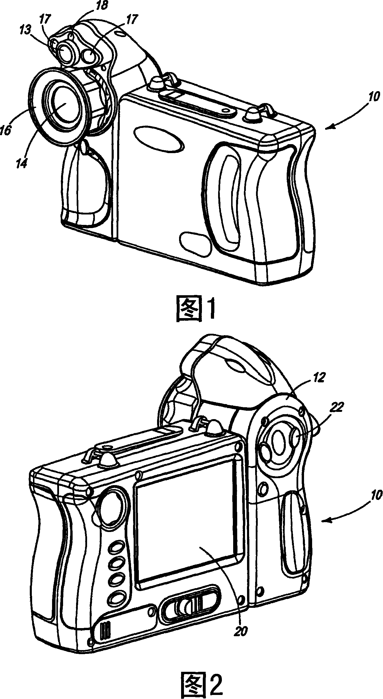
[0036] 1 and 2 are front and rear perspective views of a camera 10 according to an embodiment of the present invention. The rack includes an infrared camera module and a visible light camera module. In particular, camera 10 includes a camera housing 12, a visible light (VL) lens 13, an infrared lens 14, a focus ring 16 and a laser pointer 18, as well as various electronics located within the housing as will be described with reference to FIG. In an embodiment, LED torches / strobes 17 are located on each side of the VL lens 13 to help provide sufficient light in dark environments. The display 20 is located on the back of the camera so that infrared images, visible light images and / or mixed infrared and visible light images can be viewed. In addition, target site temperature (including temperature measurement spot size) and distance readings can be displayed. User controls 22 are also located on the back of the camera for controlling display modes...


PUM


Abstract

Methods and apparatuses for registering on a camera display separate fields of view of a visible light camera module and an infrared camera module by focusing the IR camera module. The fields of view can be displayed in several display modes including 1) full screen visible, infrared and / or blended, 2) picture-in-a-picture such as partial infrared image in a full screen visible image, and 3) infrared color alarms in visible-light images.

Description

Background technique [0001] Many infrared cameras today use only energy in the far infrared part of the electromagnetic spectrum (typically in the range of 8-14 microns) to produce images of a scene (IR images). Images obtained using these cameras assign colors or grayscale levels to the pixels making up the scene based on the intensity of the IR radiation reaching the sensor elements of the cameras. Because the synthetic IR image is based on the temperature of the object, and because the colors or levels displayed by the camera do not typically correspond to the visible color of the scene, it is difficult, especially for beginners to such devices, to map the features of interest in the IR scene (e.g., thermal Spots) are accurately associated with their corresponding locations seen by the operator in the visible light scene. Infrared-only images can be especially difficult to interpret in applications where the contrast of the infrared scene is low. [0002] Infrared sights ...

Claims


Application Information

Patent Timeline
Patent Type & Authority Applications(China)
IPC IPC(8): G01J5/00
CPCH04N5/2258H01L27/14625G01J5/025H04N5/332H04N5/23212H04N5/2254G01J5/089G01J5/0295G01C3/08G01J5/0896G01J5/0265H04N5/23293G01J5/0859H01L27/14618H04N5/33H01L2924/0002G01J5/07H04N23/45H04N23/67H04N23/635H04N23/11H01L2924/00
Inventor K·R·约翰逊T·J·麦克马纳斯
Owner JOHN FLUKE MFG CO INC
Why Eureka
Try Eureka