Systems and methods for controlling aircraft flaps and spoilers

A technology for spoilers and aircraft, which is used in aircraft control, indicating the direction of movable elements of aircraft, aircraft parts, etc., and can solve problems such as reducing system versatility, increasing system complexity and weight, etc.

Active Publication Date: 2008-01-30
THE BOEING CO
View PDF1 Cites 26 Cited by
  • Summary
  • Abstract
  • Description
  • Claims
  • Application Information

AI Technical Summary

Problems solved by technology

In some cases, these features can increase system...

Method used


Image

  • Systems and methods for controlling aircraft flaps and spoilers
  • Systems and methods for controlling aircraft flaps and spoilers
  • Systems and methods for controlling aircraft flaps and spoilers

Examples


Embodiment Construction

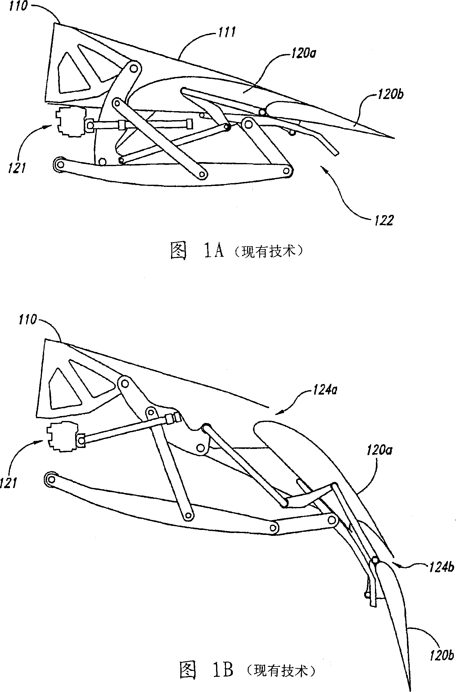
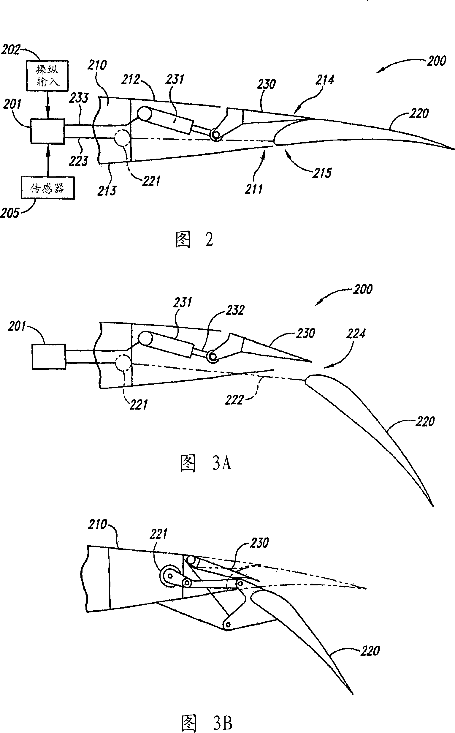
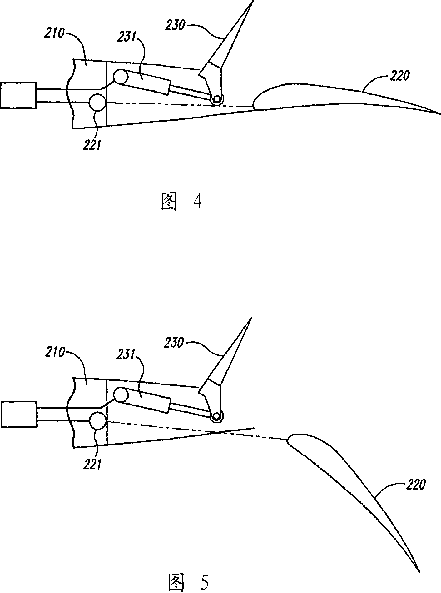
[0013] SUMMARY OF THE INVENTION Systems and methods are described for controlling aircraft flaps and spoilers, including configurations in which actuation of the flaps is mechanically independent of actuation of the spoiler. Certain specific details are set forth in the ensuing description and in Figures 2-6 to provide a thorough understanding of various embodiments of the invention. Well-known structures, systems, and system-related methods have not been shown or described in detail to avoid unnecessarily obscuring the description of the various embodiments of the invention. Furthermore, those skilled in the art will appreciate that additional embodiments of the invention may be practiced without some of the details described below.

[0014] Many embodiments of the invention described below may employ a controller in the form of computer-executable instructions, including programs executed by a programmable computer or, alternatively, by a non-programmable electronic device. ...


PUM


Abstract

Systems and methods for controlling aircraft flaps and spoilers. Systems in accordance with some embodiments include a wing having a trailing edge, and a flap positioned proximate to the wing trailing edge and being deployable relative to the wing between a first flap position and a second flap position by operation of a first actuator. A spoiler can be positioned at least proximate to the trailing edge and can be movable among at least three positions, including a first spoiler position in which the spoiler forms a generally continuous contour with an upper surface of the wing, a second spoiler position deflected downwardly from the first, and a third spoiler position deflected upwardly from the first. A second actuator can be operatively coupled to the spoiler to move the spoiler among the first, second and third spoiler positions in a manner that is mechanically independent of the motion of the flap.

Description

technical field [0001] The present invention relates to systems and methods for controlling aircraft flaps and spoilers. Background technique [0002] Current commercial transport aircraft typically include deployable high-lift devices that change the shape of the aircraft's wings according to flight conditions. These devices may include leading-edge flaps and / or slats, as well as trailing-edge flaps, which are extended during takeoff and landing to increase lift and retracted during flight to reduce aircraft drag. Commercial transport aircraft may also include spoilers to selectively reduce lift during descent, landing, roll maneuvers, and aborted takeoff. [0003] FIG. 1A is a partially schematic cross-sectional view of an airfoil 110 formed according to the prior art. The wing 110 may include a trailing edge 111 , a forward flap 120a extending aft of the trailing edge 111 , and an aft flap 120b extending aft of the forward flap 120a. A mechanical linkage 122 connects t...

Claims


Application Information

Patent Timeline
IPC IPC(8): B64C9/20B64C9/32
CPCB64D2045/001Y02T50/44B64C9/16B64C9/323B64C9/32Y02T50/32Y02T50/30Y02T50/40
Inventor 罗伯特·J·布利格尼尔·V·休因约翰·A·斯坦德利斯科特·佩珀布赖恩·L·博克希
Owner THE BOEING CO
Why Eureka
Try Eureka