Electronic lock with automatic power supply

An automatic power supply and electronic lock technology, applied in the field of electronic locks, can solve the problems of limiting electronic locks, power consumption not meeting requirements, trouble, etc., and achieve the effect of reducing failure rate and stabilizing power consumption

Inactive Publication Date: 2008-02-27
吴斐
View PDF0 Cites 3 Cited by
  • Summary
  • Abstract
  • Description
  • Claims
  • Application Information

AI Technical Summary

Problems solved by technology

The internal structure of the electronic locks currently on the market is often opened and closed by a battery-driven motor. When the battery in the electronic lock is out of power, the electronic unlocking function cannot be used. Only a mechanical key is used to unlock the lock.
Before using it again, it is very troublesome to open the lock box to replace or charge the battery;
[0003] In addition, due to the strict requirements on power consumption of electronic locks, the power consumption of existing battery-powered electronic locks cannot meet the requirements, resulting in a high failure rate of electronic locks
These problems limit the promotion of electronic locks to the direction of home use. How to solve the current problems of electronic locks has become a problem to be solved in the electronic lock industry

Method used


Image

  • Electronic lock with automatic power supply
  • Electronic lock with automatic power supply
  • Electronic lock with automatic power supply

Examples


Embodiment Construction

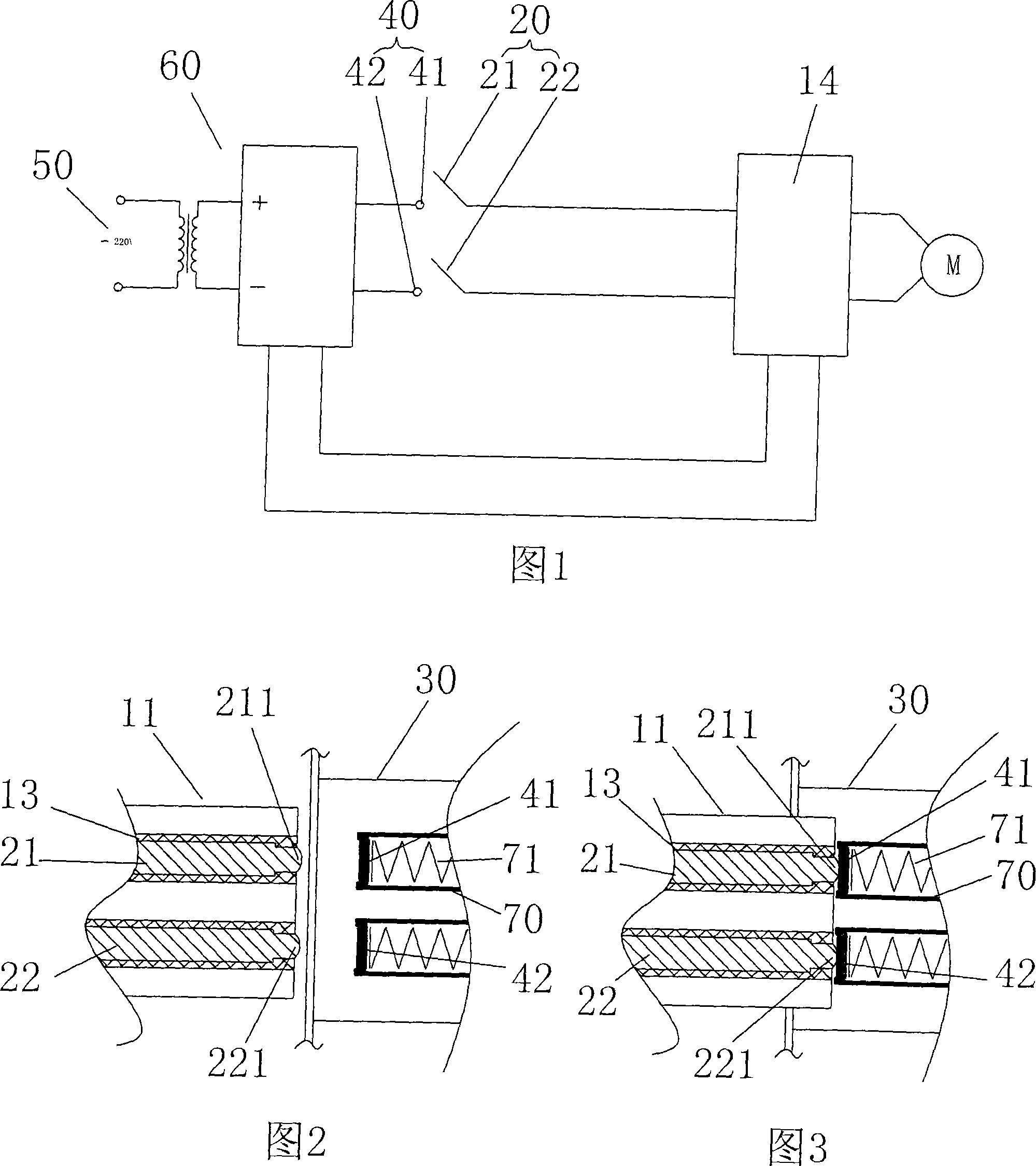
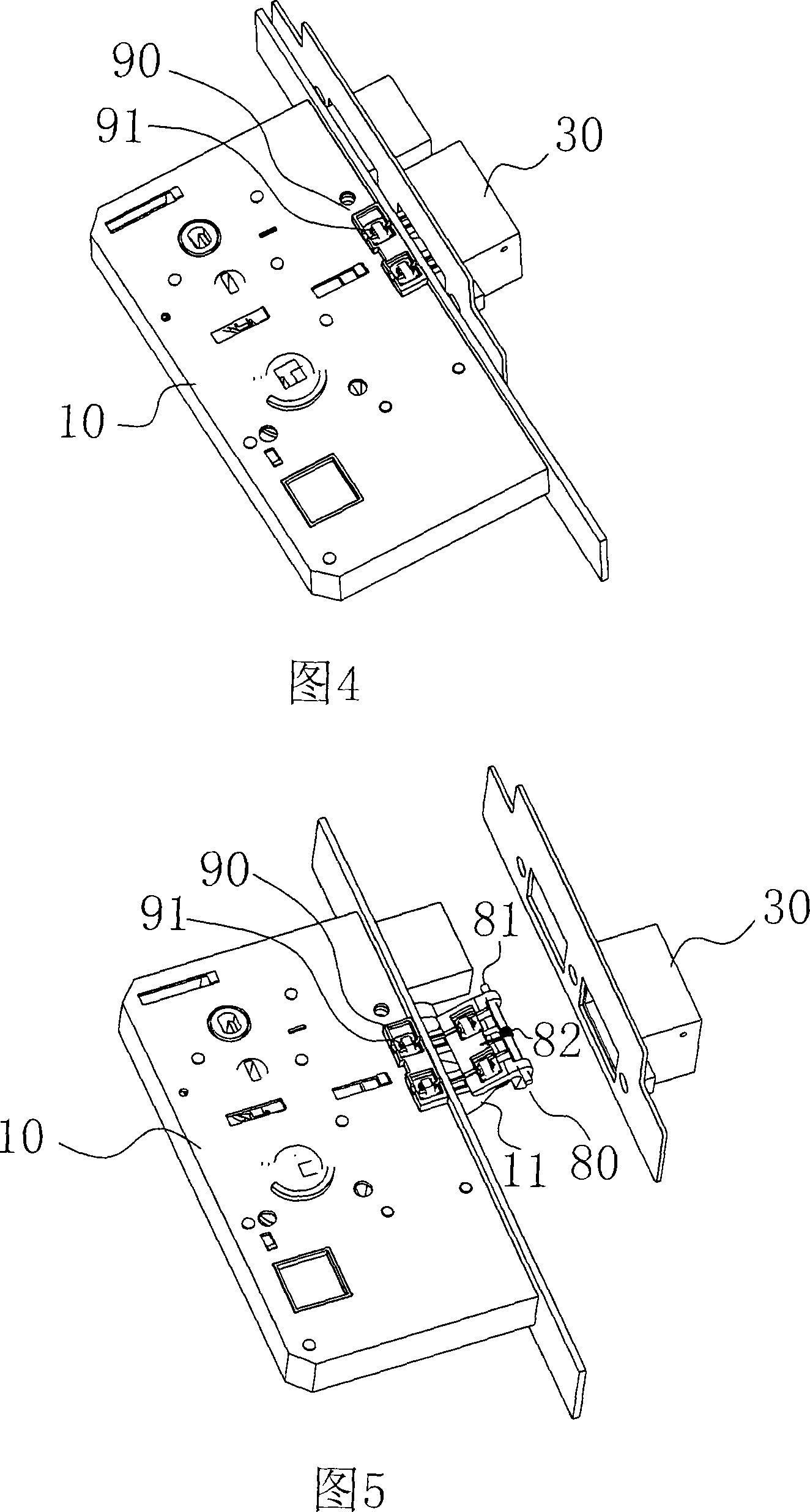
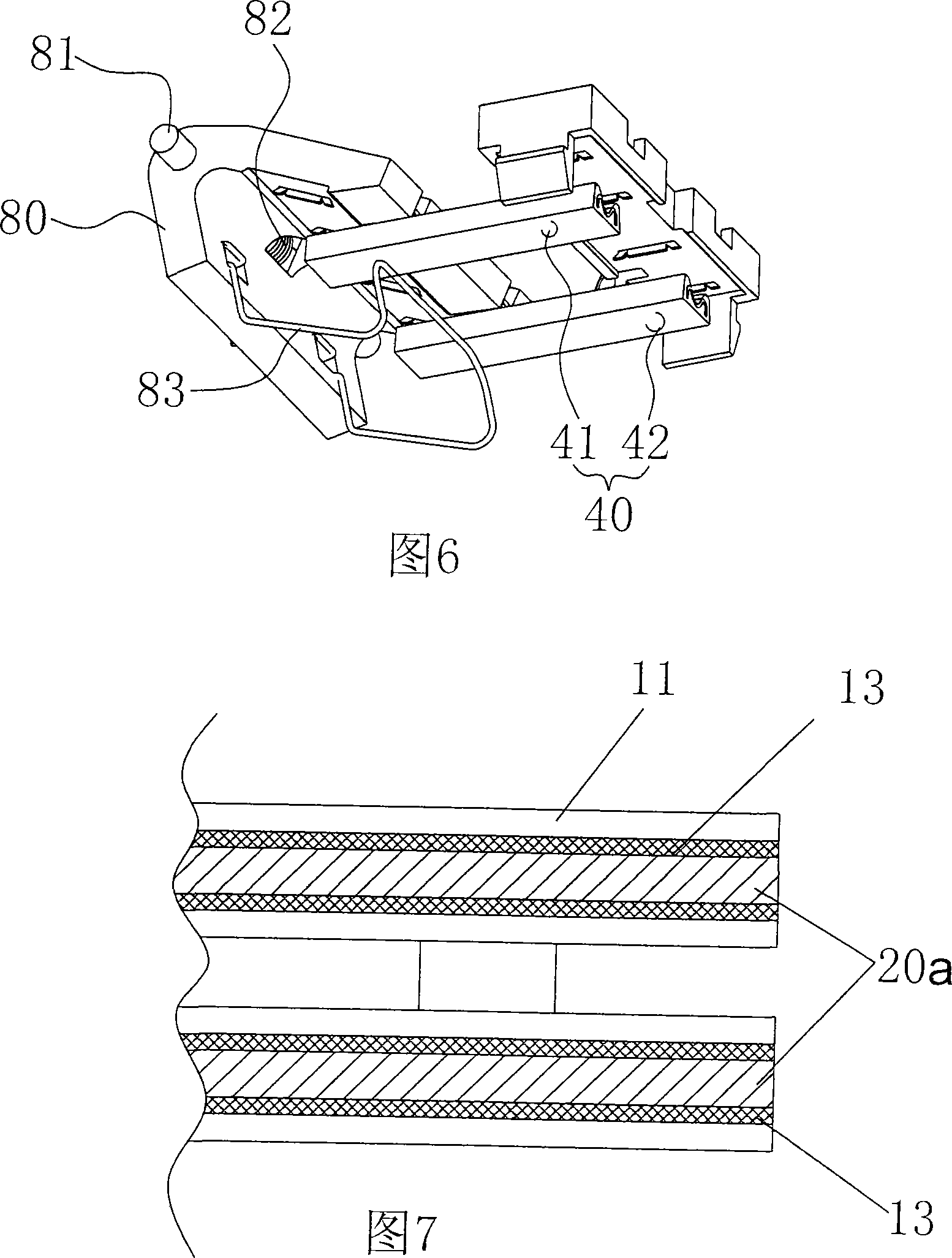
[0014] As shown in Figure 1, the present invention includes an electronic lock body 10, two conductive terminals 20 are arranged in a deadbolt 11 in the electronic lock body 10, and a button box 30 corresponding to the deadbolt 11 is provided with a The two conductive sheets 40 corresponding to the above-mentioned conductive terminals 20 are connected to the positive conductive sheet 41 and the negative conductive sheet 42 in the door buckle box 30 through the charging transformer circuit 60 respectively. The conductive terminal 21 and the negative conductive terminal 22 are respectively electrically connected to the two ends of the power supply circuit 14 connected to the motor in the electronic lock body 10; The conductive terminal 21 is connected with the positive conductive sheet 41 in the door buckle box 30 , and the negative conductive terminal 22 in the lock bolt 11 is connected with the negative conductive sheet 42 in the door button box 30 . As shown in FIGS. 2-3 , an...


PUM


Abstract

The present invention relates to electronic lock technology, and is especially one kind of electronic lock capable of being powered automatically. The electronic lock includes one electronic lock body, in which there are two conducting terminals set inside the lock bolt, two corresponding conducting tabs in the door box, one AC power source connected through one charging and voltage varying circuit to the conducting tabs, and one motor with power supplying circuit connected the conducting terminals. When the electronic lock is in locking state, the conducting terminals are connected separately to the conducting tabs. The electronic lock with low power consumption has lower battery replacing frequency and high reliability.

Description

technical field [0001] The invention relates to the technical field of electronic locks, in particular to an electronic lock capable of automatically supplying power. Background technique [0002] With the development of the lock industry, various electronic locks emerge in an endless stream. Because electronic locks are more convenient to use, they are widely used in various fields such as hotels and restaurants. The internal structure of the electronic locks currently on the market is often opened and closed by a battery-driven motor. When the battery in the electronic lock is out of power, the electronic unlocking function cannot be used. Only a mechanical key is used to unlock. Before using it again, it is very troublesome to open the lock box to replace or charge the battery; [0003] In addition, because electronic locks have strict requirements on power consumption, the power consumption of existing battery-powered electronic locks cannot meet the requirements, resul...

Claims


Application Information

Patent Timeline
Patent Type & Authority Applications(China)
IPC IPC(8): E05B47/06
Inventor 吴斐
Owner 吴斐
Why Eureka
Try Eureka