Drive circuit for plasma display screen

A technology for driving circuits and plasmas, which can be used in static indicators, instruments, identification devices, etc., and can solve problems such as excessive power consumption

Inactive Publication Date: 2005-04-06
SOUTHEAST UNIV
View PDF0 Cites 2 Cited by
  • Summary
  • Abstract
  • Description
  • Claims
  • Application Information

AI Technical Summary

Problems solved by technology

Excessive power consumption has always been a major problem in the plasma display drive circuit. As a new type of plasma display, the conductive grid type plasma display also has the same pro

Method used


Image

  • Drive circuit for plasma display screen
  • Drive circuit for plasma display screen
  • Drive circuit for plasma display screen

Examples


Embodiment Construction

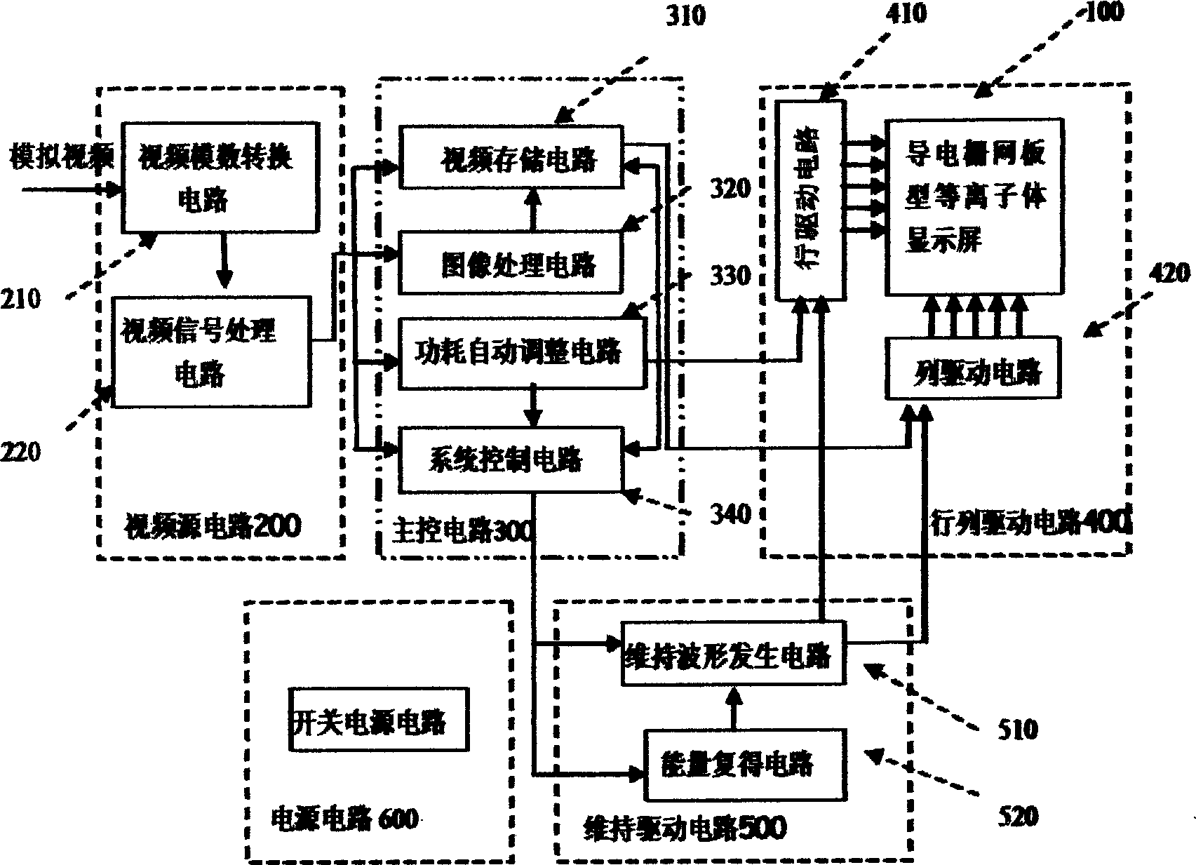
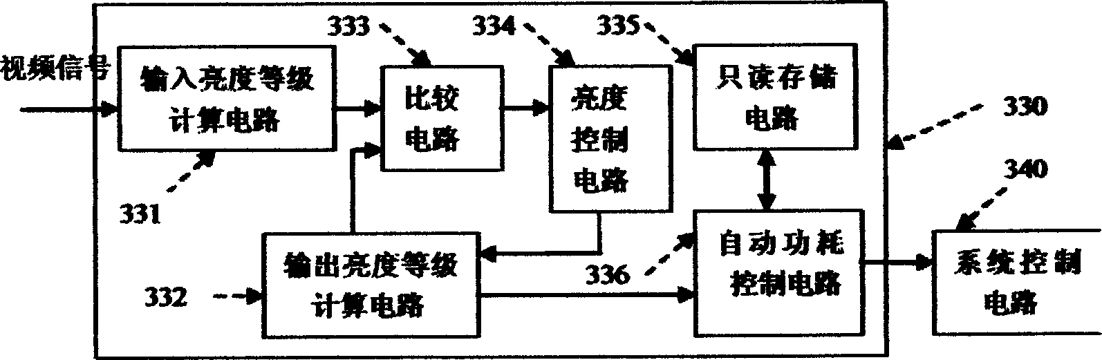
[0041] On the basis of the above-mentioned invention, further consider specific implementation schemes, and propose the following examples. In the video source 200 of this driving circuit, the input terminal of video analog-to-digital conversion circuit 210 is connected with analog video signal, and the output terminal is connected with video signal processing circuit 220; The input terminal of image processing circuit 320 in the main control circuit 300 is connected with video signal The output terminal of the processing circuit 220, the output terminal of the image processing circuit 320 is connected to the video storage circuit 310, the output terminal of the video storage circuit 310 is connected to the column drive circuit 420, and the output terminal of the power consumption automatic adjustment circuit 330 is connected to the system control circuit 340 and the system control circuit 340 respectively. The input end of the row driving circuit 410, the input end of the syst...


PUM


Abstract

It is a plasm screen drive circuit, wherein, the video conversion circuit input end of its video frequency source is connected with analog video signals and output end is connected with video signal process circuit. The image process circuit input end of the main control circuit is connected with the output end of the video signal process circuit and output end is connected with video storage circuit. The output end of the video storage circuit is connected with line drive circuit. The output end of the power self-adjusting circuit is connected with the input ends of system control circuit and row drive circuit. The output end of the system control circuit is connected with the input ends of sustain wave generating circuit and energy regain circuit.

Description

technical field [0001] The utility model relates to a plasma display screen that is applied to drive a conductive grid screen type, especially uses power consumption to automatically adjust the circuit, improves the peak brightness, and stabilizes the power consumption of the whole machine within a certain safe range to ensure the conductive grid screen type plasma display screen. Plasma display drive circuit stability. Background technique [0002] To complete the display of full-color dynamic images such as TVs or computer display terminals, a conductive grid-type plasma display must have a reliable gray-scale display method. According to the usual video display requirements, dynamic images are displayed at a speed of 50 frames per second, that is, a frame of still images is displayed every 20 milliseconds. The storage timing method divides the display time of one frame of image into several subfields, and each subfield includes an addressing peri...

Claims


Application Information

Patent Timeline
IPC IPC(8): G09F9/313G09G3/288
Inventor 汤勇明沈建于郑姚生吴忠
Owner SOUTHEAST UNIV
Why Eureka
Try Eureka