Blocked scan rebuilding and space assembly method of large object image-forming with cone-beam CT

A block scanning, large object technology, applied in the field of medical equipment

Inactive Publication Date: 2010-05-26
NORTHEASTERN UNIV LIAONING
View PDF5 Cites 0 Cited by
  • Summary
  • Abstract
  • Description
  • Claims
  • Application Information

AI Technical Summary

Problems solved by technology

The result obtained by this approach is to solve the practical problem of volumetric imaging of large objects with cone-beam CT in some less demanding situations

Method used


Image

  • Blocked scan rebuilding and space assembly method of large object image-forming with cone-beam CT
  • Blocked scan rebuilding and space assembly method of large object image-forming with cone-beam CT
  • Blocked scan rebuilding and space assembly method of large object image-forming with cone-beam CT

Examples


specific Embodiment 1

[0070] Specific embodiment 1: the block local reconstruction of Shepp-Logan mold, as Figure 10 Shown:

[0071] Step 1. Divide the Shepp-Logan mold into 5 blocks, such as Figure 5 shown;

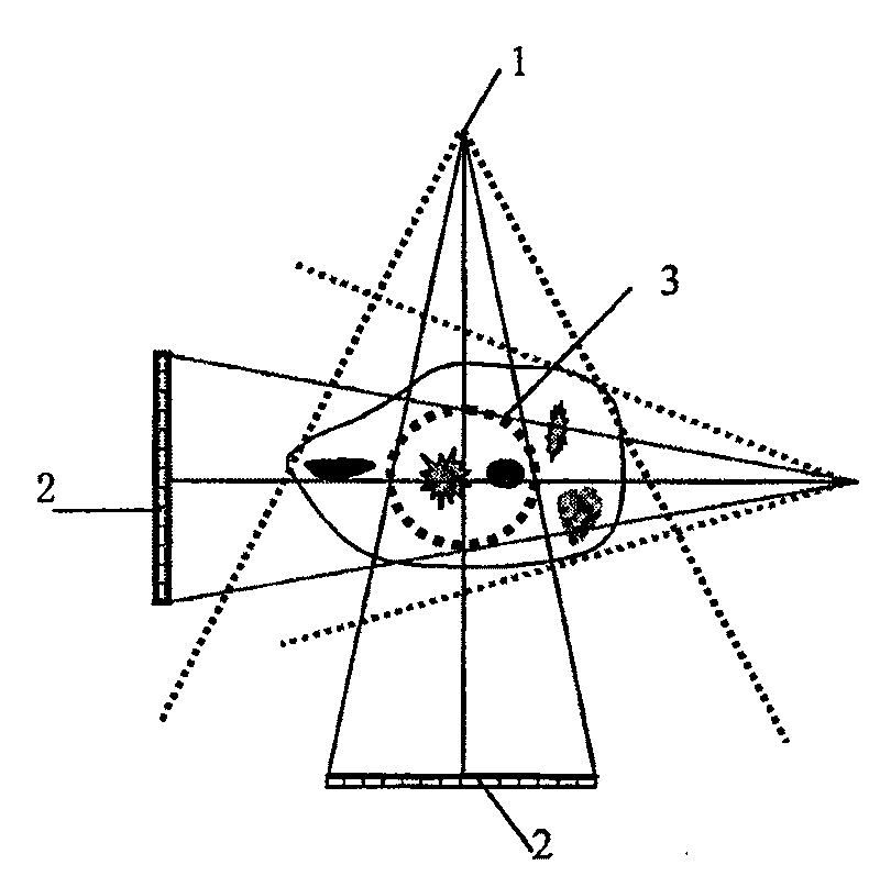
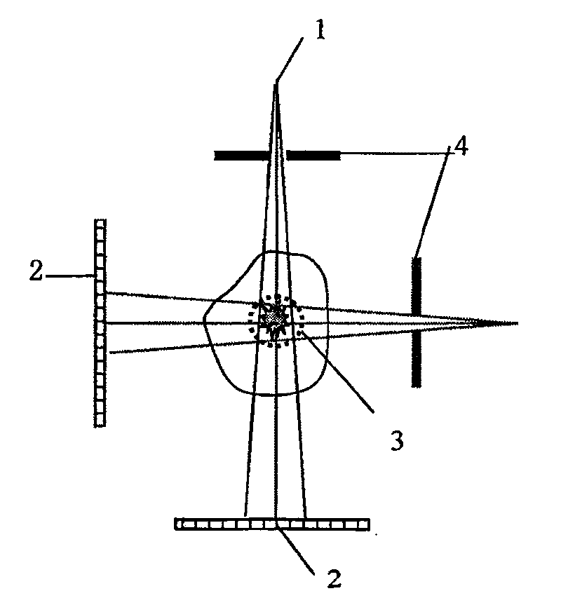
[0072] Step 2. Place each segmented area of ​​the Shepp-Logan mold in the scanning field of view of the cone beam CT, that is, in the rotation of the turntable

[0073] In the heart area, each block area is sequentially placed in the scanning field of view of cone beam CT by using the method of spatial translation;

[0074] Step 3: Cone beam scanning is performed on each partition of the Shepp-Logan mold to obtain cone beam projection images. A full scan acquires about 300 projection images. Half scans acquire about 160 images.

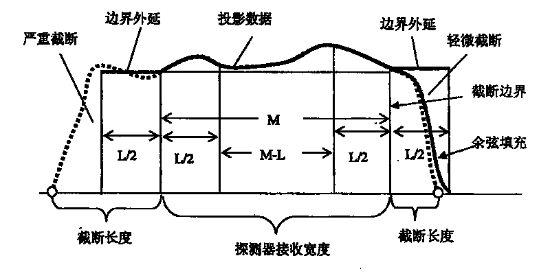
[0075] Step 4, filling the truncated area of ​​the projected image, such as figure 2 shown;

[0076] Step 5, adopt FDK method or convolution back projection method to carry out three-dimensional volume reconstruction, adopt the method of convolution back pro...

specific Embodiment 2

[0079] Specific embodiment 2: filling the data of the projected truncated image of the breast mold;

[0080] Figure 8 (a) Cone beam projection image of the breast cast without transverse truncation; Figure 8 (b) Transversely truncated projected images caused by adjusting the ray collimator; Figure 8 (c) Transversely truncated projected image after boundary extension filling.

[0081] Figure 9 is the partially reconstructed image of the breast mold; the first row shows the case of transverse truncated projection without padding (see Figure 8 Partial reconstruction of (b)), you can see the Gibbs effect caused by boundary truncation, which is manifested as a very bright edge in the reconstructed image; the second line shows that after the horizontal truncated projection is filled (see Figure 8 Local reconstruction of (c)), where the Gibbs effect is reduced and the reconstruction performance is improved in the region near the boundary.


PUM


Abstract

The method comprises: making the partitioning scan for a large object; after making an edge fill-up for the across direction cutting-off projected picture, then combining the reconstructed image blocks to get a 3D fault volume image.

Description

technical field [0001] The invention belongs to the technical field of medical instruments, in particular to a block scanning reconstruction and space assembling method for large object imaging by cone beam CT. Background technique [0002] Currently, CT scanning with cone beams is moving from scientific research to product development. Varian Medical Systems of the United States specializes in the production of flat panel detectors for cone beam CT. The best-selling flat panel detector panel in the market is Paxscan4030CB. Many universities and companies in the United States are researching cone beam CT systems, such as the University of Rochester, the University of California, Davis, Duke University, and Philips Medical Systems in Cleveland. Their R&D focuses on algorithm and system development, and local volume reconstruction of cone-beam helical scanning with PI-line reconstruction theory, and does not involve tomographic imaging of large objects with cone-beam CT. The...

Claims


Application Information

Patent Timeline
Patent Type & Authority Patents(China)
IPC IPC(8): G01N23/04G06T1/00
Inventor 陈自宽
Owner NORTHEASTERN UNIV LIAONING
Why Eureka
Try Eureka