Control scheme for dc/ac cycloconverter

A converter and half-cycle technology, applied in the direction of converting irreversible DC power input to AC power output, conversion equipment that can be converted to DC without intermediate conversion, AC power input conversion to DC power output, etc.

Inactive Publication Date: 2008-03-05
GM GLOBAL TECH OPERATIONS LLC
View PDF0 Cites 15 Cited by
  • Summary
  • Abstract
  • Description
  • Claims
  • Application Information

AI Technical Summary

Problems solved by technology

This will average out fluctuations in the output (i.e., the node between capacitor C and Hall effect sensor H) and node V

Method used


Image

  • Control scheme for dc/ac cycloconverter
  • Control scheme for dc/ac cycloconverter
  • Control scheme for dc/ac cycloconverter

Examples


Embodiment Construction

[0053] specific implementation plan

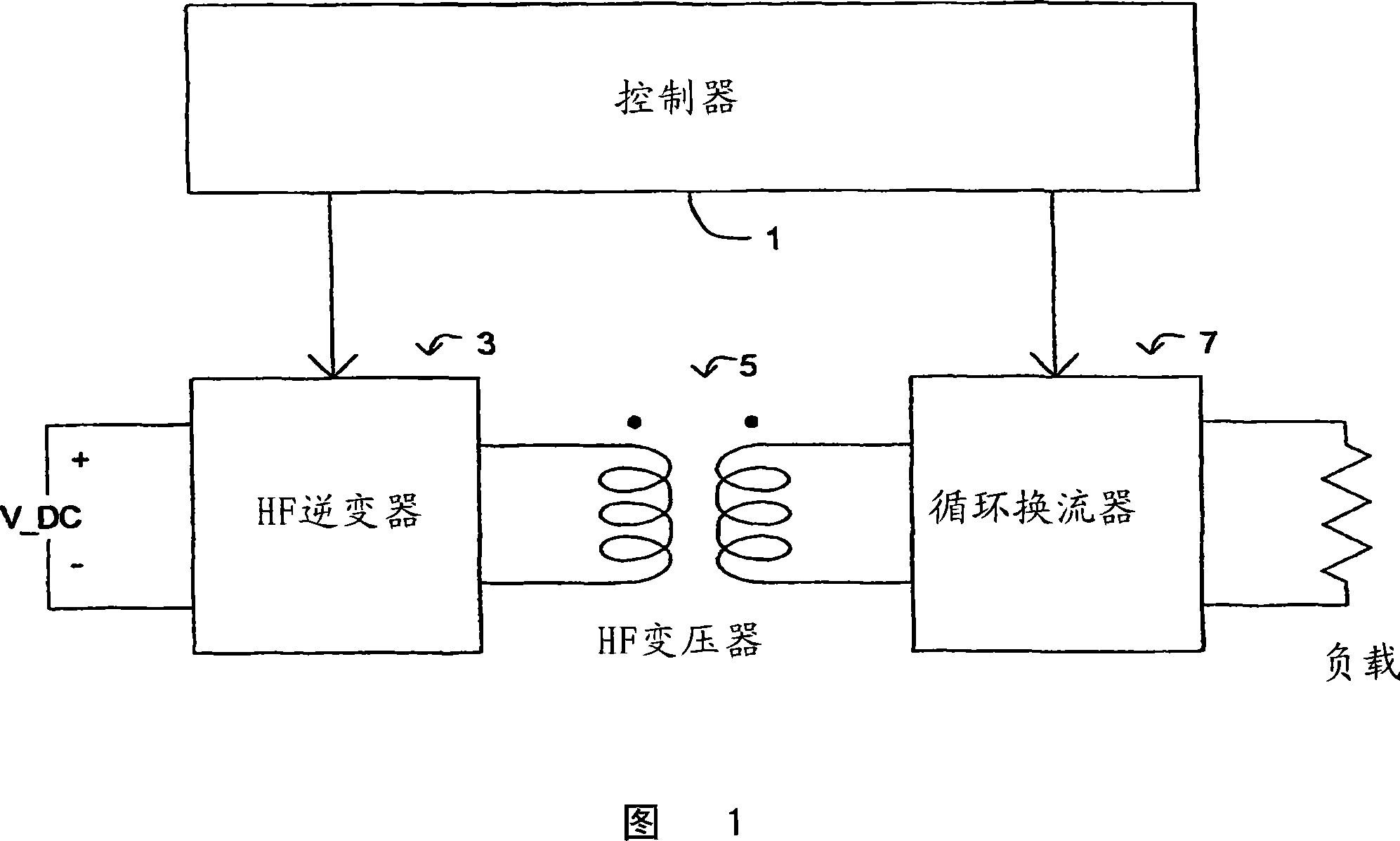
[0054] With the known commutation scheme described above, the HF transformer 5 must be sized to receive the full DC link voltage in a 50% duty cycle. The magnetic material in the transformer must be sized to avoid saturation with the length of the applied power pulse. This scheme also has HF output inductor current commutation issues during low frequency zero current detection leading to premature burnout of commutation components and noise.

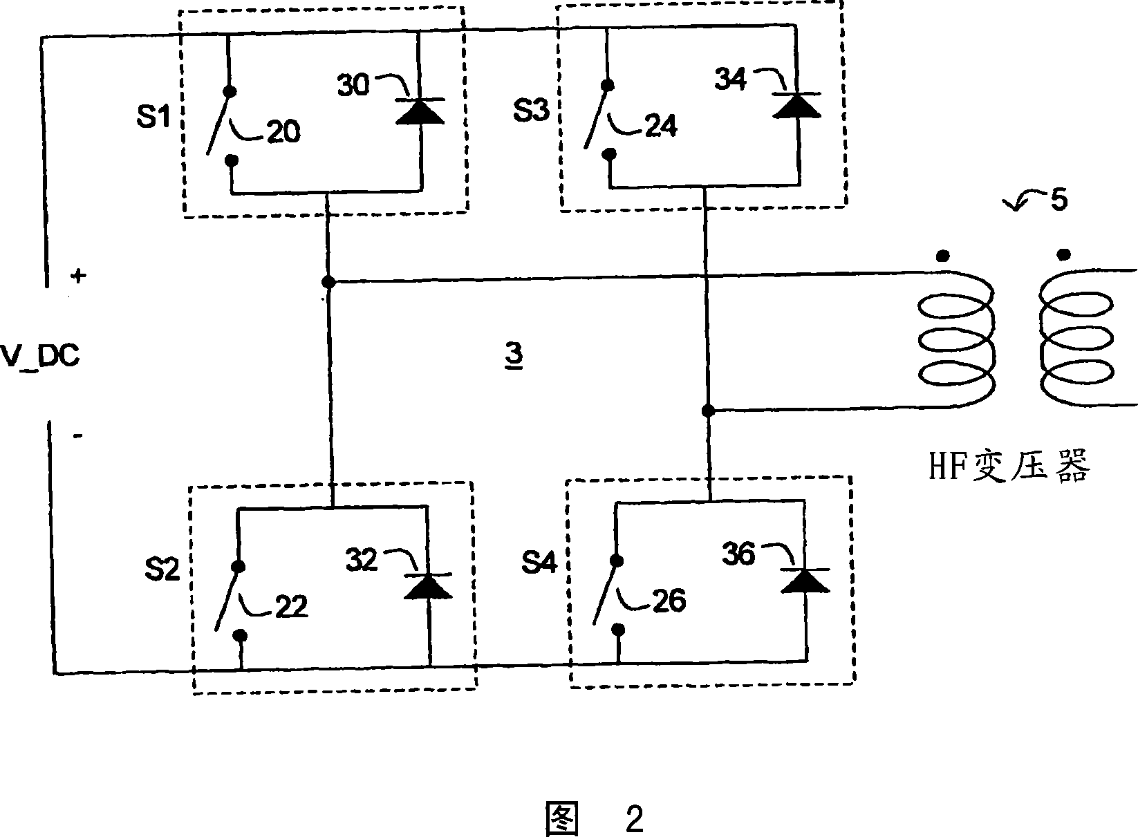
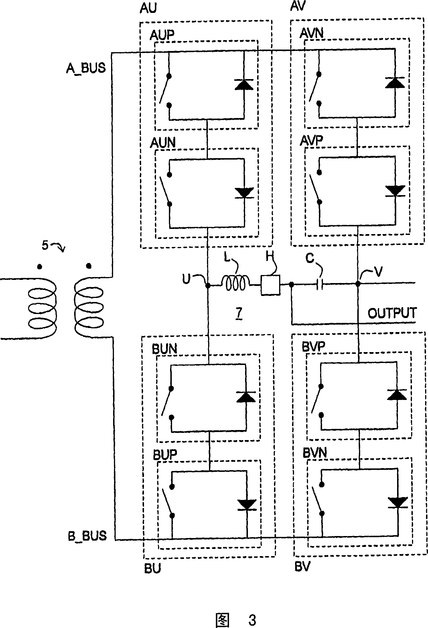
[0055] However, in the present invention, the controller 1 controls the HF inverter 3 and the cycloconverter 7 so that a more economical transformer 5 can be used. The controller 1 controls the switches S1, S2, S3 and S4 of the HF inverter 3 (FIG. 2) so that the switches S1 and S3 or the switches S2 and S4 are connected whenever the cycloconverter 7 is in the idle FW cycle. pass. This ensures that the voltage across the primary winding of the HF transformer 5 is short-circuited to zero when the cy...


PUM


Abstract

A method includes controlling the cyclo-converter 7 in coordination with controlling a coupled HF inverter 3 . The controlling of the cyclo-converter 7 provides at least a first freewheeling FW period in the cyclo-converter for each cycle of the HF inverter 3 . The controlling of the HF inverter provides a freewheeling period in the HF inverter 3 each time the first freewheeling period is provided in the cyclo-converter.

Description

technical field [0001] The present invention relates to electric vehicles and hybrid electric vehicles. In particular, the invention relates to auxiliary power systems used by such vehicles to provide auxiliary power. Background technique [0002] The assignee of the present invention designs and develops electric and hybrid electric vehicles and powertrains for use therein. The prior art relating to power systems includes descriptions of auxiliary power systems in which the main power system for road wheel drive is tapped to provide auxiliary power for other purposes. The auxiliary power system can be used to provide power to other electrical appliances that are typically built into or accompany the vehicle, such as radios, headlights, air conditioners, hair dryers, etc. At other times, the auxiliary power system may be called upon to provide power to appliances that are often "plugged" into the vehicle, such as lighters and power packs for charging cell phones, laptops, ...

Claims


Application Information

Patent Timeline
Patent Type & Authority Applications(China)
IPC IPC(8): H02M7/44H02M5/22
CPCH02M7/538
Inventor L·A·卡尤克S·希蒂
Owner GM GLOBAL TECH OPERATIONS LLC
Why Eureka
Try Eureka