Stereo drainage system structure for landfill underground water

A system structure, landfill technology, applied in infrastructure engineering, construction, etc., can solve the problems of destroying the anti-seepage layer, polluting the groundwater quality, poor adaptability, etc., to ensure the anti-seepage effect, safety, and reliable water quality assurance Effect

Active Publication Date: 2010-05-19
ZHONGYE-CHANGTIAN INT ENG CO LTD
View PDF2 Cites 0 Cited by
  • Summary
  • Abstract
  • Description
  • Claims
  • Application Information

AI Technical Summary

Problems solved by technology

This dredging method is suitable for landfills where the upstream mountains are not high, the water catchment area is small, and the groundwater is not abundant; but for areas with high mountains and steep slopes and rich groundwater, its adaptability is relatively poor, resulting in some landfills After the site is completed and put into operation, the groundwater level at the bottom of the landfill site will rise during the rainy season, especially during heavy rain, which will cause "water pockets" in the anti-seepage membrane.
If it is not controlled, it may even break the anti-seepage membrane, destroy the anti-seepage layer, and cause the anti-seepage layer to lose its anti-seepage effect, which will cause sewage leachate to flow into the groundwater system and pollute the groundwater quality. The consequences are disastrous

Method used


Image

  • Stereo drainage system structure for landfill underground water
  • Stereo drainage system structure for landfill underground water
  • Stereo drainage system structure for landfill underground water

Examples


Embodiment Construction

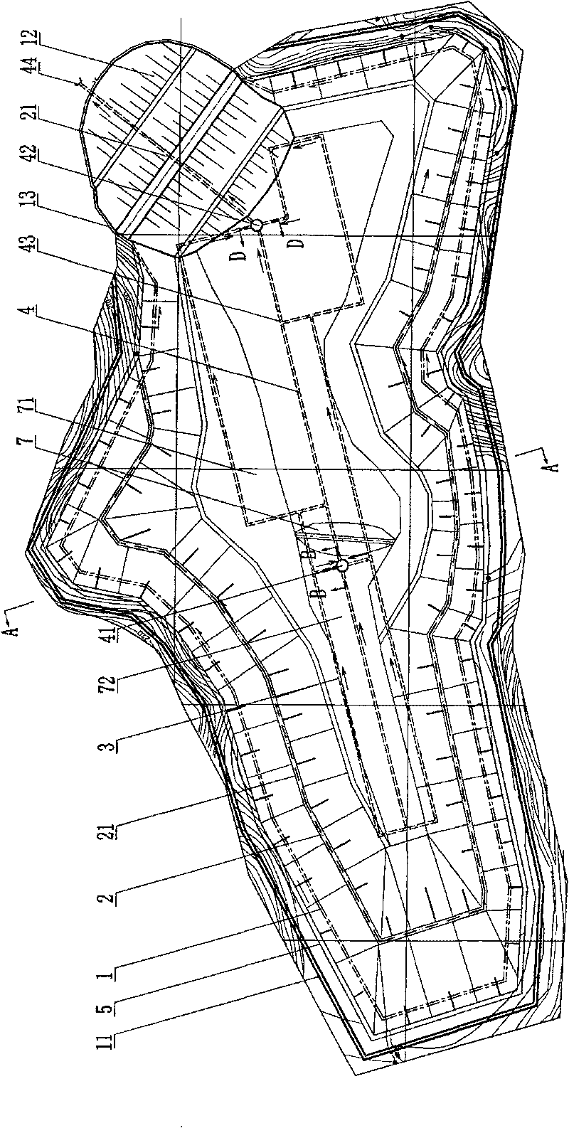
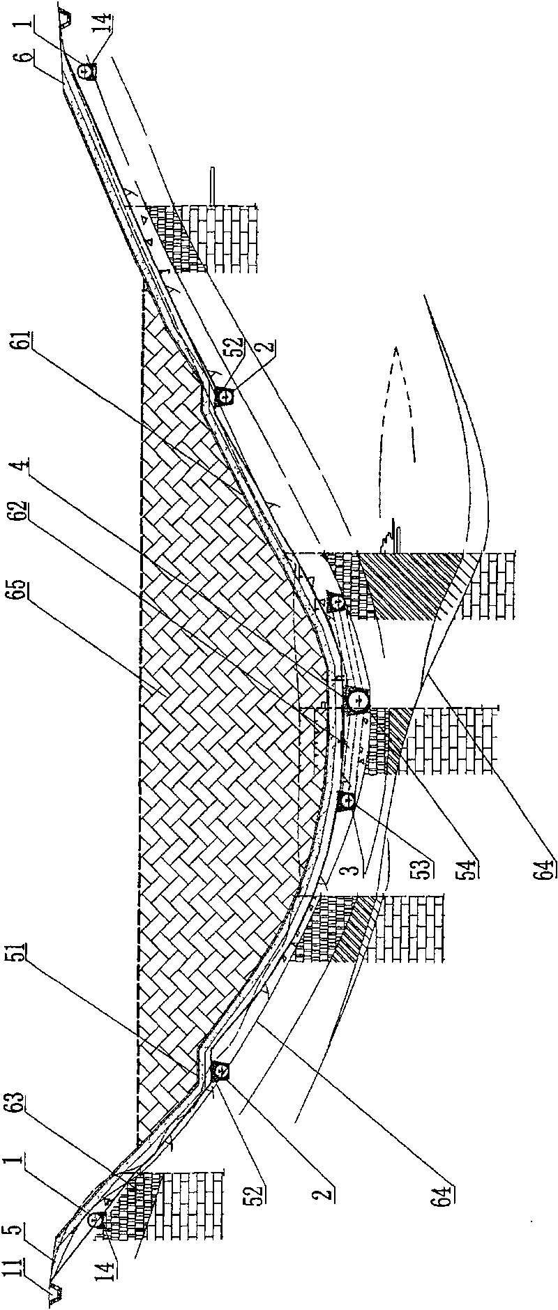
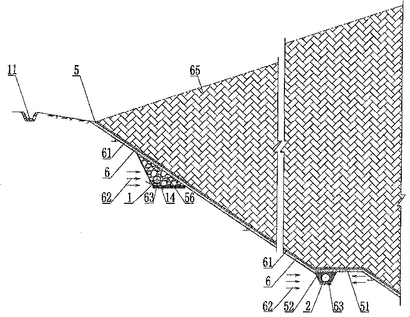
[0043] like Figure 1 to Figure 13 Shown, a kind of three-dimensional dredging system structure of landfill groundwater of the present invention, the water retaining embankment 7 in the middle of the landfill site area divides the landfill area of ​​the landfill site into the east part of the anti-seepage layer landfill area 71 And the non-paved anti-seepage layer filling area 72 in the west, the sewage interception dam 12 of the landfill is built at the northeast ditch mouth of the paved anti-seepage layer landfill area. An anti-seepage layer 6 is laid on the bottom of the landfill area 71 with the anti-seepage layer laid. The anti-seepage layer 6 includes an anti-seepage membrane 61 laid on its upper part. The anti-seepage layer 6 includes a hydrophobic layer 62 and an impermeable water layer 63. Stratum structures, stratum boundaries 64 are used as boundaries between strata structures. Landfill waste 65 is heap-filled above the anti-seepage membrane 61 . The structure of ...


PUM


Abstract

The stereo underground water draining system for landfill includes one upper water flow cutting off structure set in the top of the slope in landfill, one bottom water draining structure set in the bottom of landfill, and water cutting off open ditches. The upper water flow cutting off structure includes permeated water cutting off pipes around the landfill; the water cutting off open ditches dugin the periphery of the landfill have outlet in the downstream of the landfill; and the permeated water cutting off pipes are communicated to outside landfill or to the bottom water draining structure. The water draining system may have also middle water flow cutting off structure and foot water flow cutting off structure communicated mutually. The water draining system can drain underground waterand surface water effectively to ensure the antiseepage effect of the impervious barrier.

Description

technical field [0001] The invention relates to a drainage system structure for groundwater in a landfill, in particular to a three-dimensional drainage system structure for groundwater in a landfill. Background technique [0002] At present, hazardous waste (industrial solid waste) and municipal solid waste landfill sites are generally located in remote mountainous areas. In order to reduce the amount of landfill work and save investment, most landfill sites use valley sites , built in a deep ditch or depression surrounded by mountains on three sides. These sites generally have dense vegetation, high mountains and steep slopes, and large water catchment areas, so it is easy to cause surface water and seepage water from higher hillsides around the landfill to flow into the bottom of the landfill. Most modern landfills adopt horizontal anti-seepage. In order to control the highest water level of groundwater, make it lower than the anti-seepage layer at the bottom of the lan...

Claims


Application Information

Patent Timeline
Patent Type & Authority Patents(China)
IPC IPC(8): E02D19/20
Inventor 王又武刘石桥陈章友吴利玲周玉莲
Owner ZHONGYE-CHANGTIAN INT ENG CO LTD
Why Eureka
Try Eureka