Method for controlling a filter maintenance indicator

A technology of indicators and liquid filters, applied in chemical instruments and methods, separation methods, filtration and separation, etc., can solve the problems of increasing the pressure damage of the main casing of the transmission

Active Publication Date: 2008-03-26
ALLISON TRANSMISSION INC
View PDF0 Cites 8 Cited by
  • Summary
  • Abstract
  • Description
  • Claims
  • Application Information

AI Technical Summary

Problems solved by technology

A clogged or clogged transmission filter can cause damage by increasing the pressure inside the main transmission case

Method used


Image

  • Method for controlling a filter maintenance indicator
  • Method for controlling a filter maintenance indicator
  • Method for controlling a filter maintenance indicator

Examples


Embodiment Construction

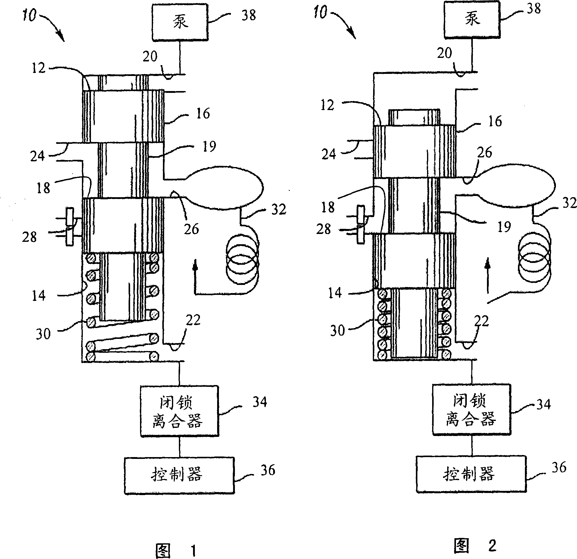
[0020] Referring to the drawings, in which like reference numerals designate like parts, a filter state detection device 10 is illustrated in FIG. 1 . The device 10 includes a valve 12 housed in a cavity 14 . Valve 12 is movable from a first position, shown in FIG. 1 , to a second position, shown in FIG. 2 . Valve 12 preferably includes a first land 16 and a second land 18 connected by an intermediate shaft portion 19 . The first and second lands 16 , 18 have the same diameter which is larger than the diameter of the intermediate shaft portion 19 . Cavity 14 has a first inlet 20 , a second inlet 22 , an outlet 24 , a switch port 26 , and an activation port 28 . Fluid enters cavity 14 through first inlet 20 at an inlet pressure equal to the inlet pressure of the fluid filter (ie, transmission fluid pressure) and through second inlet 22 into cavity 14 at an outlet pressure equal to the filter's discharge pressure. Liquid entering the first inlet 20 impacts the valve 12, tendi...


PUM


Abstract

A method for determining the condition of a transmission fluid filter and controlling an operator indicator to alert the operator that the fluid filter requires replacement is disclosed. The method includes monitoring a fluid pressure switch, determining an operating mode of the transmission, determining whether the operating mode of the transmission is changing, activating a timer if the operating mode is changing, recording the time, comparing the time to a predefined time threshold, determining whether the recorded time is greater than the predefined threshold, and activating the operator indicator to indicate that the fluid filter requires replacement if the recorded time is greater than the predefined threshold.

Description

technical field [0001] The present invention relates to a method of monitoring and diagnosing the condition of a vehicle fluid filter, especially fluid under pressure. Background technique [0002] On-road vehicles with drivetrains require lubricating fluids for continued operation. Rather, engines and especially automatic transmissions require lubricating fluids or oils to maintain their operation and prolong their service life. In addition, these fluids flow through filters to remove impurities and metal shavings generated by normal operation of the powertrain. The lubricating fluid and the filter need to be replaced regularly during the use of the vehicle. Typically, the engine fluid and filter replacement intervals are different from the transmission fluid and filter replacement intervals. Vehicle owners or drivers often do not know when these fluids and filters need to be replaced. As a result, many times the lubricating fluid and filter are used without replacement...

Claims


Application Information

Patent Timeline
Patent Type & Authority Applications(China)
IPC IPC(8): F16H57/04B60R17/00G01M99/00
CPCF16H57/0402B01D35/143
Inventor J·S·沙图克S·E·穆恩迪M·A·莱恩斯J·E·舒尔茨
Owner ALLISON TRANSMISSION INC
Why Eureka
Try Eureka