

Trigger switch
A technology of triggering switches and triggers, which is used in electrical switches, electrical components, portable mobile devices, etc., to achieve the effect of small bottom area
- Summary
- Abstract
- Description
- Claims
- Application Information
AI Technical Summary
Problems solved by technology
Method used
Image

Examples
Embodiment Construction
[0051] Hereinafter, embodiments of the present invention will be described with reference to the drawings.
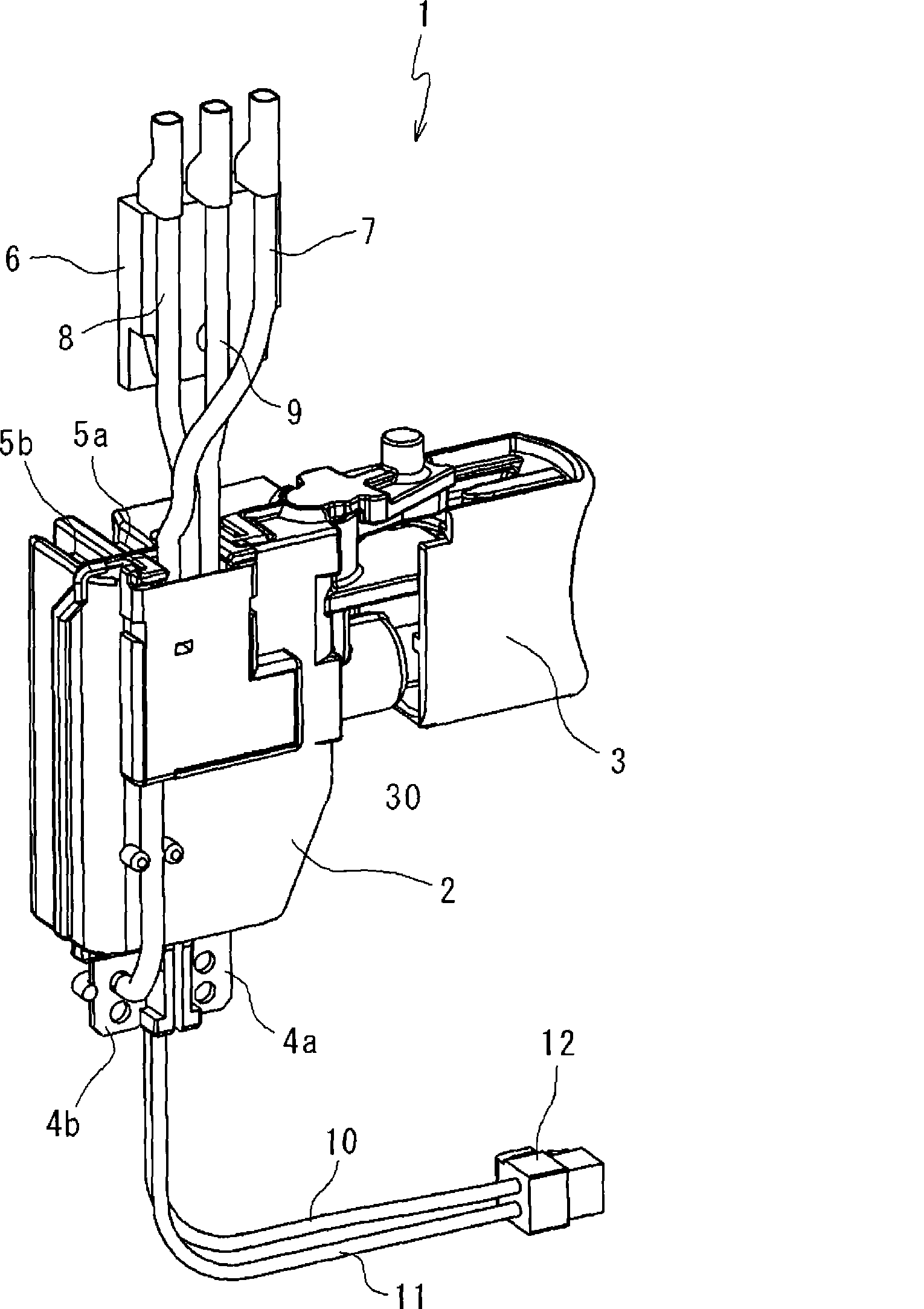
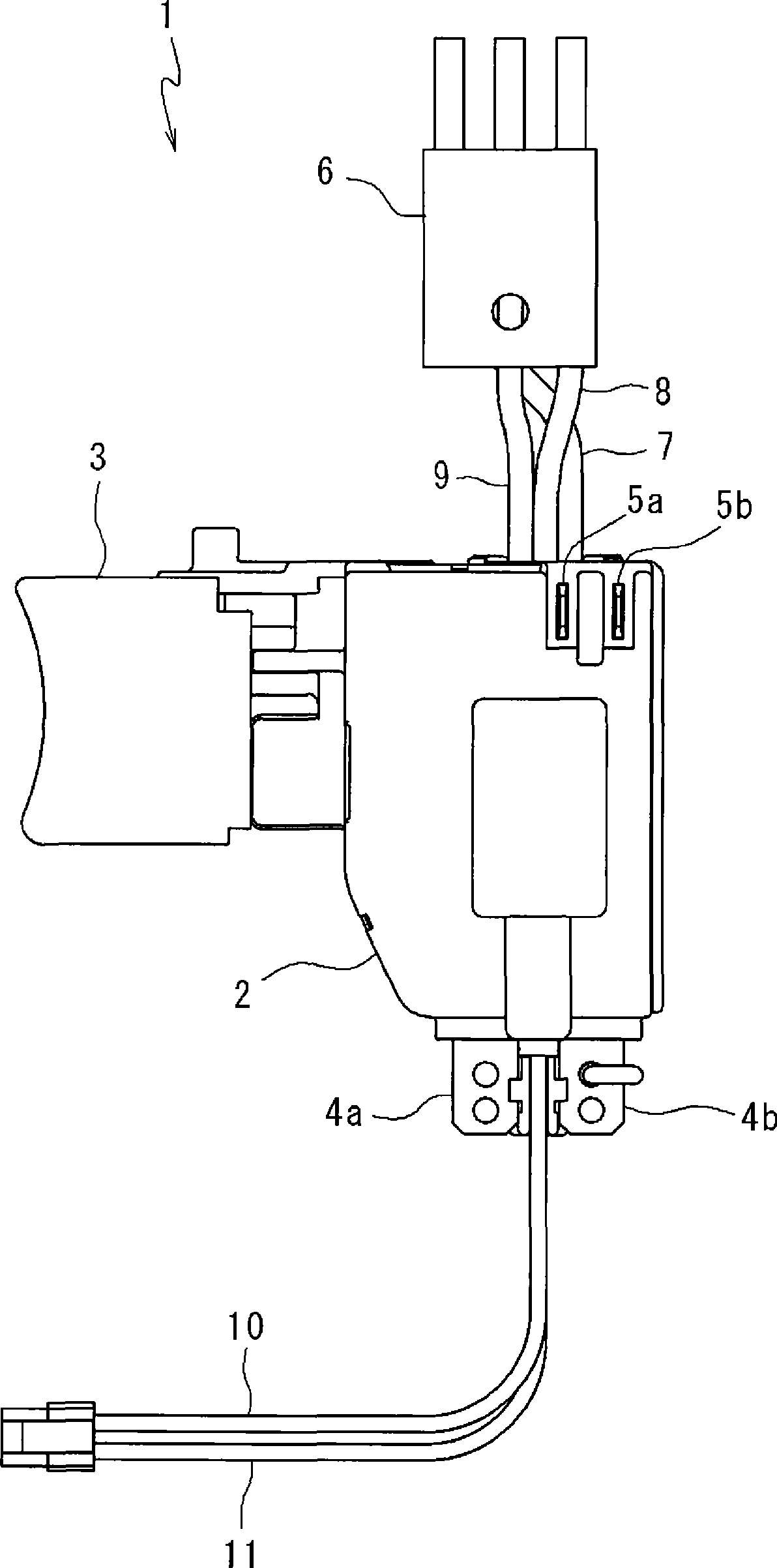
[0052] figure 1 as well as figure 2 A trigger switch 1 as one embodiment of the present invention is shown. The trigger switch 1 is incorporated into the handle of the cordless electric tool to control the rotational speed of a motor that drives a tool of the cordless electric tool.
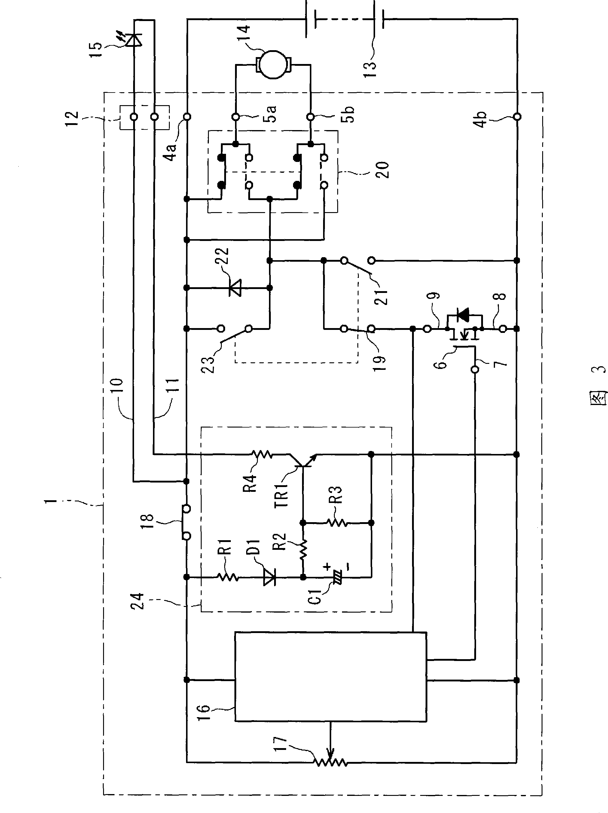
[0053] The trigger switch 1 includes a frame body 2 made of insulating resin, and a user pushes it in with fingers (引き む) trigger 3, and has a pair of power supply terminals 4a, 4b connected to an external power supply, and a pair of output terminals 5a, 5b connected to an external motor. In order to dissipate heat, the switching element 6 is arranged outside the housing 2 and is connected to a circuit housed inside the housing 2 via insulated wires 7 , 8 , and 9 . In addition, the trigger switch 1 leads out a pair of lead wires 10, 11 from the housing 2, and can be connected to an ...
PUM
 Abstract
Description
Claims
Application Information