Method of welding L type aluminum alloy section agitating friction welding

An aluminum alloy profile, friction stir welding technology, applied in welding equipment, welding/welding/cutting items, non-electric welding equipment, etc., can solve problems such as special shape, uneven thickness of profiles, etc., to enhance plastic flow and improve heat deficiency , to achieve the effect of high-quality welding

Inactive Publication Date: 2010-06-16
JIANGSU UNIV OF SCI & TECH
View PDF6 Cites 0 Cited by
  • Summary
  • Abstract
  • Description
  • Claims
  • Application Information

AI Technical Summary

Problems solved by technology

[0005] The technical problem to be solved by the present invention is: for the technical difficulties caused by the uneven thickness and special shape of the aluminum alloy profile with special shape when stirring welding, the existing technology is difficult to achieve the desired effect, and a A friction stir welding method suitable for special aluminum alloy profiles, such as the aluminum alloy profiles with a small boss on the inside of the long and short side ends used in the LCD TV frame

Method used


Image

  • Method of welding L type aluminum alloy section agitating friction welding
  • Method of welding L type aluminum alloy section agitating friction welding
  • Method of welding L type aluminum alloy section agitating friction welding

Examples


Embodiment 1

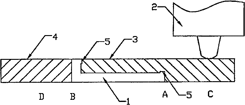
[0023] The schematic diagram of the reverse side welding work of the present invention is as figure 2 As shown, the short side of the L-shaped aluminum alloy profile 1 faces upwards, and the auxiliary block A3 is an aluminum alloy block whose shape matches the inner shape of the L-shaped aluminum alloy profile. Assembled above the inner side of the L-shaped aluminum alloy profile, on the outside of the short side of the L-shaped aluminum alloy profile 1, the auxiliary pad B4 is assembled, and the auxiliary pad A3 and two butt-connected L-shaped aluminum alloy profiles 1 ( figure 2 Only the cross-section of the first L-shaped profile 1 can be seen, and the cross-section of the second L-shaped profile 1 is covered by the cross-section of the first L-shaped profile 1 . ) and the auxiliary block B4 are laterally clamped on the welding workbench by the tooling to form a rectangular cross-sectional structure.

[0024] The length of the stirring head 2 installed on the friction st...

Embodiment 2

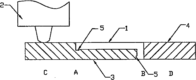
[0029] The working diagram of the front welding of the second embodiment of the present invention is as follows: image 3 As shown, the short side of the L-shaped aluminum alloy profile 1 is downward, the auxiliary pad A3 is assembled under the inner side of the L-shaped aluminum alloy profile 1, and the auxiliary pad B4 is assembled on the outside of the short side of the L-shaped aluminum alloy profile 1. The auxiliary block A3, two butted L-shaped aluminum alloy profiles 1 ( image 3 Only the cross-section of the first L-shaped aluminum alloy profile 1 can be seen, the cross-section of the second L-shaped aluminum alloy profile 1 is covered by the cross-section of the first L-shaped aluminum alloy profile 1) and the auxiliary block B4 , clamped horizontally on the welding workbench by the tooling to form a rectangular cross-sectional structure.

[0030] When welding the front side, the stirring head 2 starts to rotate from point A and inserts the auxiliary pad A3, and then...


PUM

PropertyMeasurementUnit
lengthaaaaaaaaaa

Abstract

The invention relates to a welding method for the friction stir welding of aluminum alloy section material, and belongs to the material joining technical field. The method mainly comprises back welding and front welding. An assistant cushion is arranged on the outside of a short side of L model aluminum alloy section material; another assistant cushion which is matched with the inner shape of theL model aluminum alloy section material is arranged on the inner side of the L model aluminum alloy section material. By utilizing a tooling, an assistant cushion, two butted L model aluminum alloy section material, and another assistant cushion are laterally clamped on a welding work bench, and a rectangular section structure is formed. The chief axis of a friction stir welding machine which is orderly inserted into the assistant cushion rotates, and horizontally moves to the welding direction, the welding is finished after the chief axis reaches the end point, and the stirring head is pulledout. The invention efficiently solves the special requirement that the friction stir welding technology needs to contact and fractionize and the welding position, solves the heat transfer problem ofa double-layer plate formed by the L model aluminum alloy section material after the assistant cushion is added, and realizes the high quality welding of the L model aluminum alloy section material with the special shape.

Description

technical field [0001] The invention relates to a welding method of friction stir welding, in particular to a welding method of friction stir welding of aluminum alloy profiles, belonging to the technical field of material connection. Background technique [0002] Friction stir welding (FSW) is a new low-temperature solid-phase joining technology, which is suitable for welding low-melting point alloys. Invented by The Welding Institute (TWI) in 1991 (US5460317), the principle of this technology is to use a high-speed rotating stirring head to insert into the seam, and use the strong friction and stirring of the stirring head to make the welding seam area It is in a thermoplastic state and is broken, mixed, and connected together under a certain pressure. The stirring head rotates and squeezes at high speed in the direction of welding, and the weld seam is formed behind the stirring head, thus completing the solid connection. This technology is widely used in aerospace, ship...

Claims


Application Information

Patent Timeline
Patent Type & Authority Patents(China)
IPC IPC(8): B23K20/26B23K20/12B23K103/10
Inventor 严铿赵勇聂洁刘海波付娟
Owner JIANGSU UNIV OF SCI & TECH
Why Eureka
Try Eureka