Welding method for L-shaped aluminium alloy section bar stirring friction welding

An aluminum alloy profile, friction stir welding technology, applied in welding equipment, non-electric welding equipment, metal processing equipment and other directions, can solve the problems of special shape, uneven thickness of the profile, etc., to enhance plastic flow, improve heat shortage, achieve high The effect of quality welding

Inactive Publication Date: 2018-06-29
邓七刚
View PDF2 Cites 0 Cited by
  • Summary
  • Abstract
  • Description
  • Claims
  • Application Information

AI Technical Summary

Problems solved by technology

[0005] The technical problem to be solved by the present invention is: for the technical difficulties caused by the uneven thickness and special shape of the aluminum alloy profile with special shape when stirring welding, the existing technology is difficult to achieve the desired effect, and a A friction stir welding method suitable for special aluminum alloy profiles, such as the aluminum alloy profiles with a small boss on the inside of the long and short side ends used in the LCD TV frame

Method used


Image

  • Welding method for L-shaped aluminium alloy section bar stirring friction welding
  • Welding method for L-shaped aluminium alloy section bar stirring friction welding
  • Welding method for L-shaped aluminium alloy section bar stirring friction welding

Examples


Embodiment 1

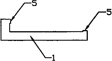
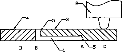
[0023] The schematic diagram of the reverse side welding work of the present invention is as figure 2 As shown, the short side of the L-shaped aluminum alloy profile 1 faces upwards, and the auxiliary block A3 is an aluminum alloy block whose shape matches the inner shape of the L-shaped aluminum alloy profile. Assembled above the inner side of the L-shaped aluminum alloy profile, on the outside of the short side of the L-shaped aluminum alloy profile 1, the auxiliary pad B4 is assembled, and the auxiliary pad A3 and two butt-connected L-shaped aluminum alloy profiles 1 ( figure 2 Only the cross-section of the first L-shaped profile 1 can be seen, and the cross-section of the second L-shaped profile 1 is covered by the cross-section of the first L-shaped profile 1 . ) and the auxiliary block B4 are laterally clamped on the welding workbench by the tooling to form a rectangular cross-sectional structure.

[0024] The length of the stirring head 2 installed on the friction st...

Embodiment 2

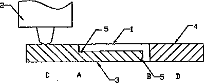
[0029] The working diagram of the front welding of the second embodiment of the present invention is as follows: image 3 As shown, the short side of the L-shaped aluminum alloy profile 1 is downward, the auxiliary pad A3 is assembled under the inner side of the L-shaped aluminum alloy profile 1, and the auxiliary pad B4 is assembled on the outside of the short side of the L-shaped aluminum alloy profile 1. The auxiliary block A3, two butted L-shaped aluminum alloy profiles 1 ( image 3 Only the cross-section of the first L-shaped aluminum alloy profile 1 can be seen, the cross-section of the second L-shaped aluminum alloy profile 1 is covered by the cross-section of the first L-shaped aluminum alloy profile 1) and the auxiliary block B4 , clamped horizontally on the welding workbench by the tooling to form a rectangular cross-sectional structure.

[0030] When welding the front side, the stirring head 2 starts to rotate from point A and inserts the auxiliary pad A3, and then...


PUM

PropertyMeasurementUnit
lengthaaaaaaaaaa

Abstract

The invention relates to a welding method for L-shaped aluminium alloy section bar stirring friction welding and belongs to the technical field of material connection. The welding method mainly comprises reverse face welding and front face welding, one auxiliary pad block is assembled on the outer side of a short edge of an L-shaped aluminium alloy section bar, the other auxiliary pad block with the shape being anastomotic with that of the inner side of the L-shaped aluminium alloy section bar is assembled on the inner side of the L-shaped aluminium alloy section bar, the auxiliary pad block,two butted L-shaped aluminium alloy section bars and the other auxiliary pad block are horizontally clamped on a welding workbench by a tooling, a rectangular section structure is formed, a main shaftof a stirring friction welding machine rotates, inserts the auxiliary pad blocks gradually, moves horizontally to welding direction points and finishes welding after reaching the end point, and a stirring head is pulled out. By means of the welding method for the L-shaped aluminium alloy section bar stirring friction welding, the problems of the stirring friction welding process requiring specialcontact friction requirements for welding portions and heat transferring of a double-deck plate formed by the L-shaped aluminium alloy section bar being added the auxiliary pad blocks are effectivelysolved, and high-quality welding of the L-shaped aluminium alloy section bars of special shapes is realized.

Description

technical field [0001] The invention relates to a welding method of friction stir welding, in particular to a welding method of friction stir welding of aluminum alloy profiles, belonging to the technical field of material connection. Background technique [0002] Friction stir welding (FSW) is a new low-temperature solid-phase joining technology, which is suitable for welding low-melting point alloys. Invented by The Welding Institute (TWI) in 1991 (US5460317), the principle of this technology is to use a high-speed rotating stirring head to insert into the seam, and use the strong friction and stirring of the stirring head to make the welding seam area It is in a thermoplastic state and is broken, mixed, and connected together under a certain pressure. The stirring head rotates and squeezes at high speed in the direction of welding, and the weld seam is formed behind the stirring head, thus completing the solid connection. This technology is widely used in aerospace, ship...

Claims


Application Information

Patent Timeline
Patent Type & Authority Applications(China)
IPC IPC(8): B23K20/12B23K20/233
CPCB23K20/122B23K20/233
Inventor 邓七刚
Owner 邓七刚
Why Eureka
Try Eureka