Converting unit of energy converter

A technology of energy converter and conversion unit, which is applied in the direction of pipe components, machines/engines, pipes/pipe joints/pipe fittings, etc.

Inactive Publication Date: 2008-04-09
张裕光 +1
View PDF0 Cites 1 Cited by
  • Summary
  • Abstract
  • Description
  • Claims
  • Application Information

AI Technical Summary

Problems solved by technology

Currently, "dark energy" cannot be tested by existing means, and the disappearance of energy in nature can only be regarded as being transformed into "dark energy".

Method used


Image

  • Converting unit of energy converter
  • Converting unit of energy converter
  • Converting unit of energy converter

Examples


Embodiment Construction

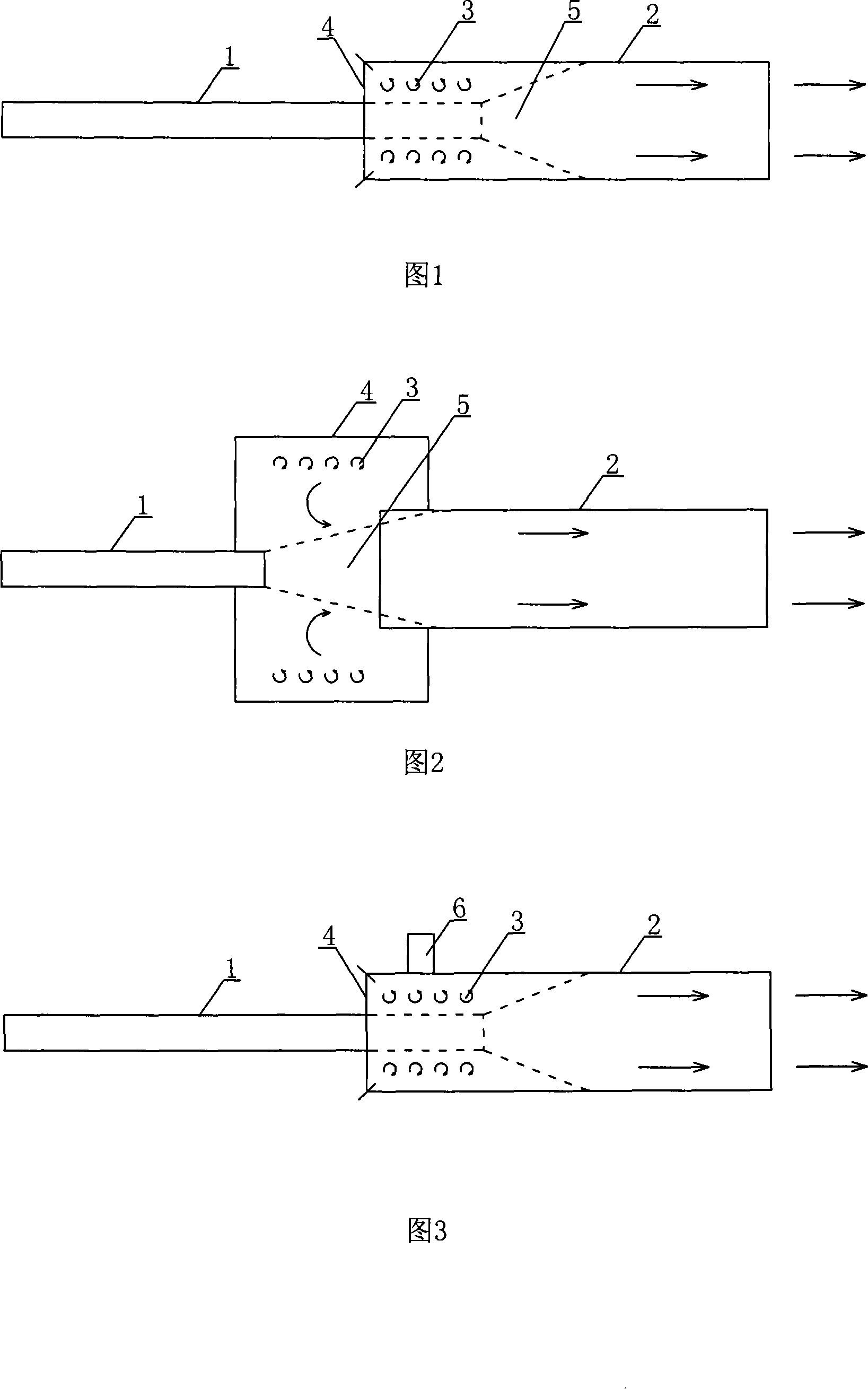
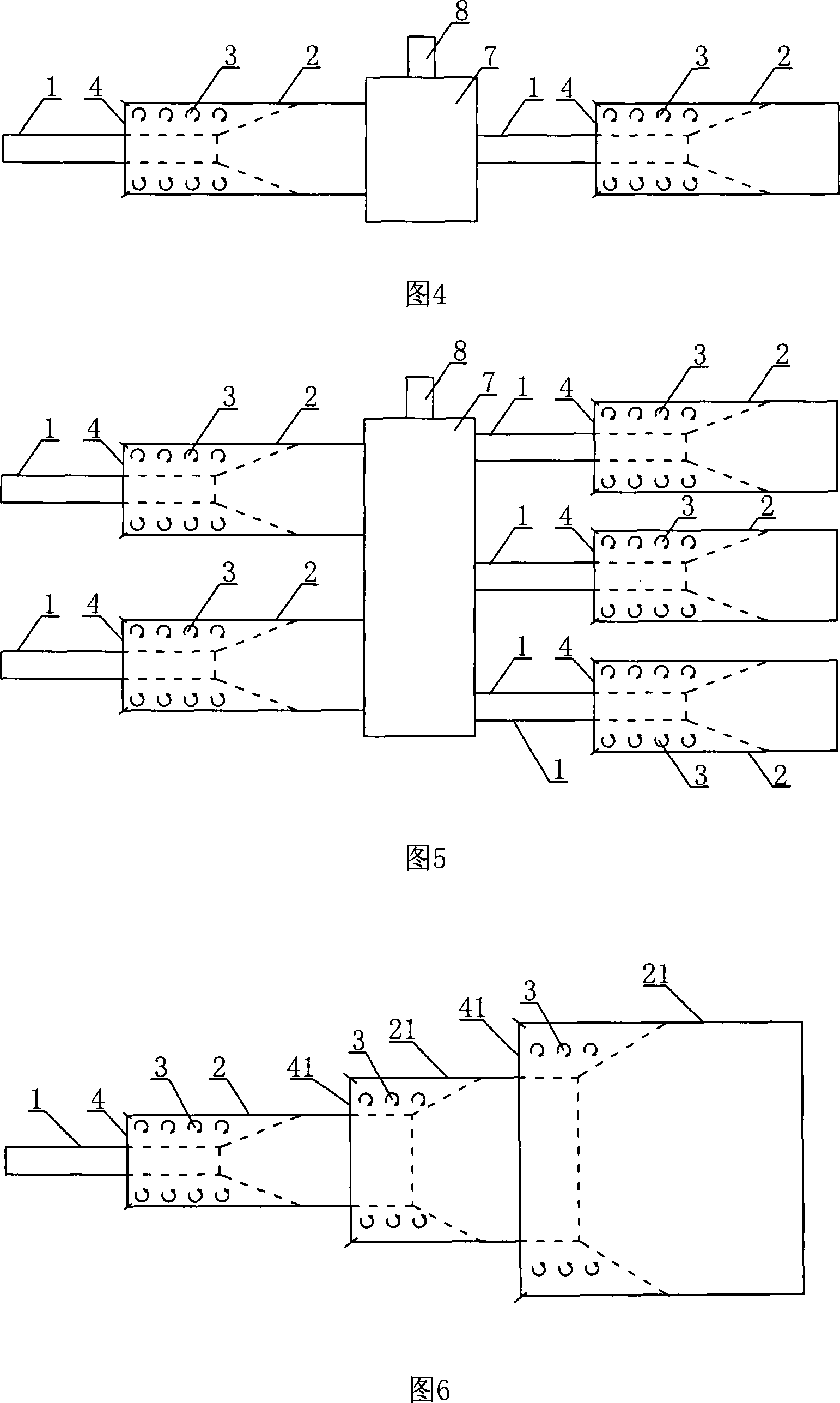
[0034]As shown in Figures 1 and 2, an energy converter gas conversion unit is composed of a gas input pipe 1 and a gas output pipe 2, the cross-sectional size of the output pipe 2 is larger than the cross-sectional size of the input pipe 1, and the gas input pipe 1 and gas output pipe 2 A sealing body 4 is connected between them, and a space 3 is left between the sealing body 4 and the gas flow 5 injected from the gas input pipe 1 into the gas output pipe 2 . When a gas with a pressure enters the output pipe 2 from the input pipe 1, an entrainment effect field is generated in the space 3, thereby generating a vacuum force in this area, which is converted into "dark energy". At this time, the gas flow rate at the output end 2 is Nearly half of the gas flow at the input end, that is, only half of the output gas, the other half has been annihilated. As shown in Figure 2, the space 3 is provided with a through pipe 6 communicating with the atmosphere or with the space 3 of other c...


PUM


Abstract

The invention discloses an energy converter conversion unit, consisting of an input pipe and an output pipe. The input pipe is extended in the output pipe or butted with the output pipe; the overlapped position between two pipes is provided with a space; the circumferences between the input pipe and the output pipe are hermetically connected; when the gas with a certain pressure enters the output pipe from the input pipe, the space at the overlapped position of the structure produces an entraining effect field, thus producing vacuum force in the area; in this way, dark energy is converted, and the gas is annihilated.

Description

Technical field [0001] The invention relates to an energy converter conversion unit. Background technique [0002] At present, after the input gas is converted, the device that reduces the output gas has not appeared so far, and it cannot be explained by the existing theory - "law of conservation of energy". However, in recent years, people have discovered through the "Hubble" space telescope that the universe is not only expanding but also "accelerating" the expansion. It can be deduced from the acceleration of expansion that it expands due to the existence of a negative pressure, that is, dark energy, and the total amount of this dark energy accounts for 73% of the energy of the entire universe. We know that dark energy exists because of its influence on the existing material world, but there is no theory that can give a reasonable explanation for dark energy. The study of this problem will surely lead to a major revolution in physics and astronomy, and eventually lead t...

Claims


Application Information

Patent Timeline
Patent Type & Authority Applications(China)
IPC IPC(8): F03G7/10
CPCF03G7/10F04F5/20F16L55/02
Inventor 张裕光张忠强
Owner 张裕光
Why Eureka
Try Eureka