Vane machine, in particular vane pump

A vane type and vane pump technology, which is applied in the direction of rotary piston machinery, mechanical equipment, rotary piston pumps, etc., can solve the problems of complicated and expensive manufacture of swing valve pumps, achieve good sealing, improve efficiency, and large delivery volume Effect

Inactive Publication Date: 2008-04-16
JOMA POLYTEC
View PDF2 Cites 16 Cited by
  • Summary
  • Abstract
  • Description
  • Claims
  • Application Information

AI Technical Summary

Problems solved by technology

However, the swing valve pump known from DE 195 32 703 C1 is complex and expensive to manufacture

Method used


Image

  • Vane machine, in particular vane pump
  • Vane machine, in particular vane pump
  • Vane machine, in particular vane pump

Examples


Embodiment Construction

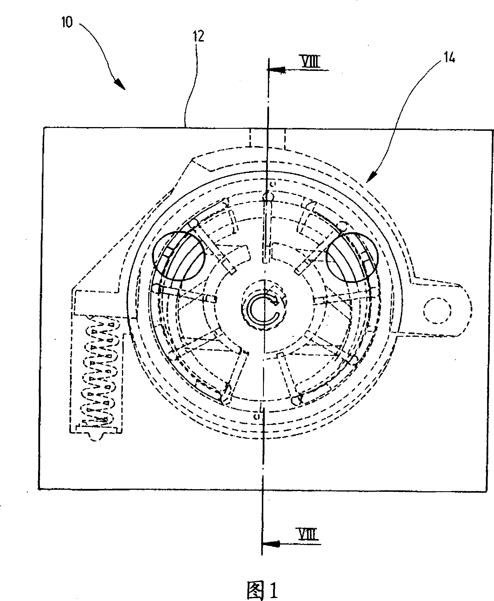
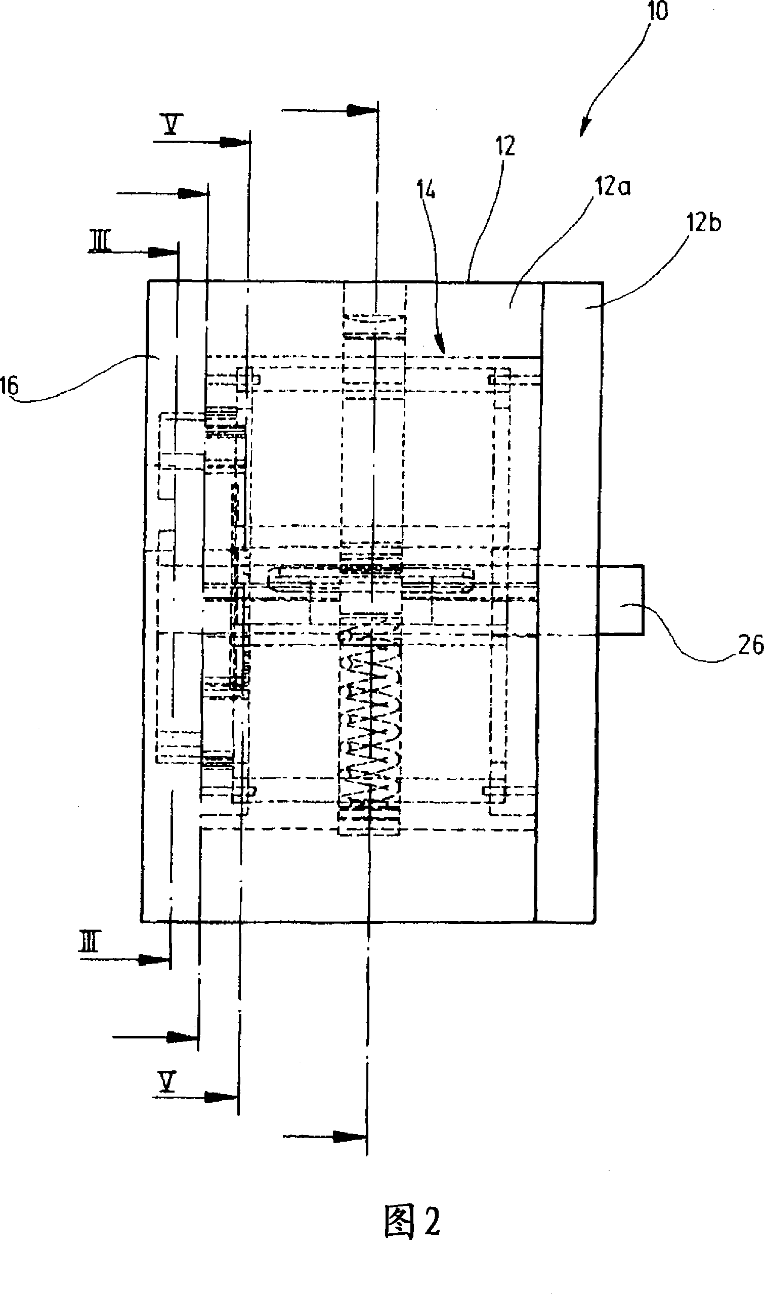
[0025] The vane pump has the reference numeral 10 as a whole in FIGS. 1-9 . It should be pointed out here that, for reasons of clarity, not all possible reference numerals are indicated in all subsequent figures. As shown in particular in FIG. 2, the vane pump includes a cylindrical housing 12 consisting of a pot-shaped part 12a and an end cover 12b. Disposed within the housing 12 is a pump assembly 14 .

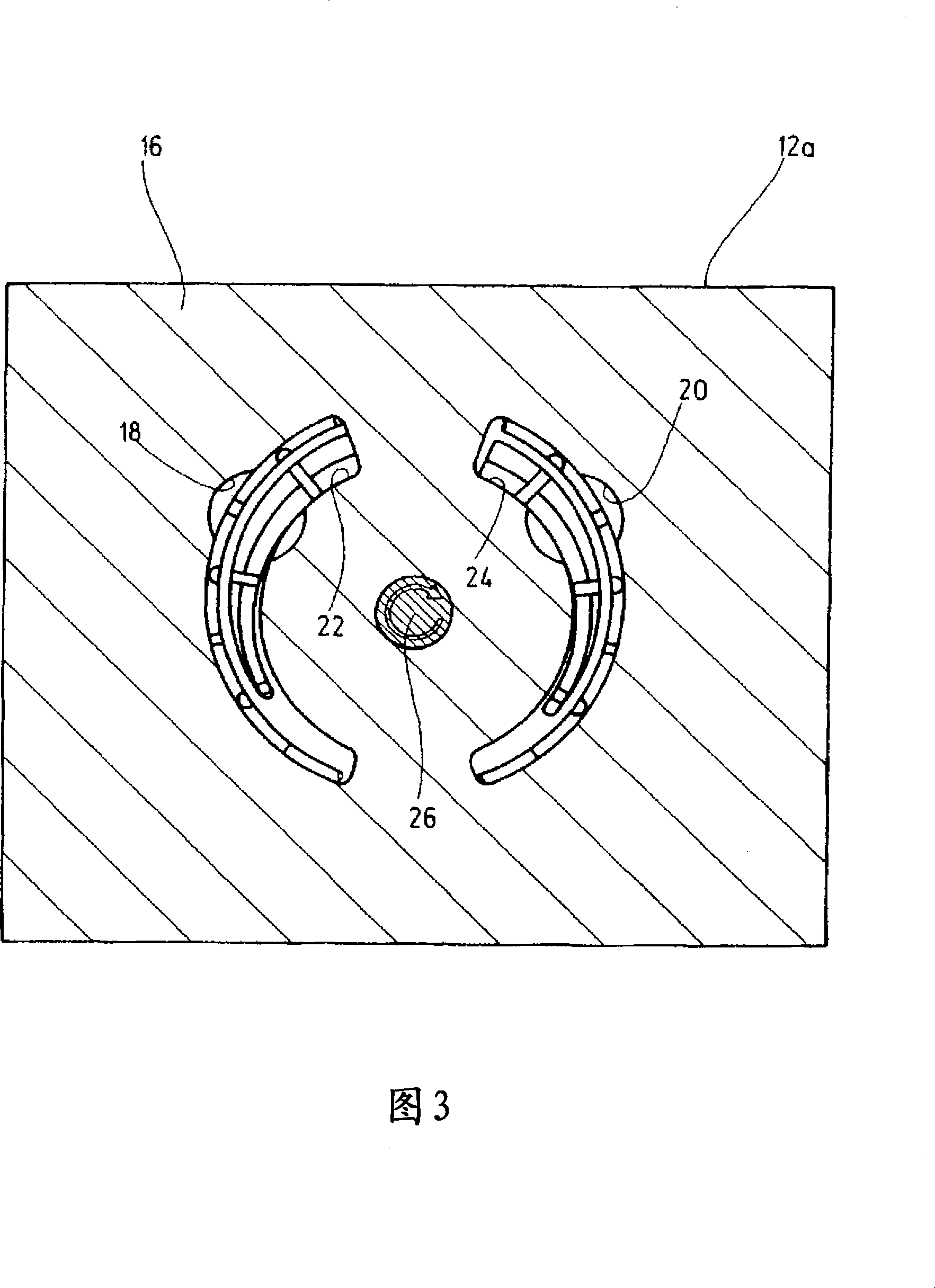
[0026] FIG. 3 shows a section III-III through a region of the base 16 of the pot-shaped section 12 a of the housing 12 from FIG. 2 . Inside this bottom 16 there is an inlet 18 and an outlet 20 which communicate with a kidney-shaped recess 22 or 24 present on the inside of the bottom 16 . Furthermore, a transmission shaft 26 is mounted on the base 16, which at its opposite end passes through the cover 12b of the housing 12 and can be connected there via a coupling not shown to a corresponding transmission.

[0027] As can be seen, for example, from FIGS. 6 and 7 , the driv...


PUM


Abstract

A vane machine comprises an inner rotor (28) and an outer rotor (51). A plurality of radially extending vane elements (32) separates first vane chambers (80) from one another. The vane elements (32), with a radially inner end region (34), are accommodated in the inner rotor (28) in a radially displaceable manner and, with a radially outer end region (36), are accommodated in the outer rotor (51) in a pivotable manner. It is proposed that the radially inner end regions (34) of the vane elements (32) be accommodated in the inner rotor (28) at a fixed angle and that the outer rotor (51) comprise individual shoes (38) which are separate for each vane element (32) and in which the vane elements (32) are accommodated in a pivotable manner.

Description

technical field [0001] The invention relates to a vane machine, in particular a vane pump, according to the preamble of claim 1 . Background technique [0002] DE 100 40 711 A1 discloses a vane pump with an annular inner rotor in which a plurality of radially outwardly extending vane elements are accommodated radially displaceable. The radially inner end regions of the blade parts are supported on a torsionally fixed central part, and the radially outer end regions are supported on a torsionally fixed outer ring. The rotor is rotatable about an axis of rotation that is offset relative to the central axis of the centerpiece and outer ring. In this way, during the rotational movement of the rotor, a delivery chamber which first increases and then decreases again is formed between the vanes. Due to the change in volume of the delivery chamber, the liquid is first drawn into the delivery chamber and then discharged again. The end regions of the vane members slide on the cente...

Claims


Application Information

Patent Timeline
Patent Type & Authority Applications(China)
IPC IPC(8): F04C2/344
CPCF04C2/3445F04C14/226F04C2/344
Inventor 维利·施奈德
Owner JOMA POLYTEC
Why Eureka
Try Eureka