Clutch controlling apparatus and clutch controlling method
A clutch control, clutch technology, applied in transmission control, toothed components, belts/chains/gears, etc., can solve problems such as difficult to verify the reliability and stability of control actions, and achieve the effect of preventing shifting shocks
- Summary
- Abstract
- Description
- Claims
- Application Information
AI Technical Summary
Problems solved by technology
Method used
Image

Examples
no. 1 approach
[0028] Hereinafter, preferred embodiments of the present invention will be specifically described with reference to the drawings. Figure 1 to Figure 5 Shown is the first embodiment of the clutch control device of the present invention. As an example, such as Figure 9 As shown, the clutch control device 100 of the first embodiment is installed on a transmission 110 of an engineering vehicle, such as a wheel loader. The output of the engine E of the wheel loader is decelerated by the transmission 110 and then transmitted to the wheels 120 .
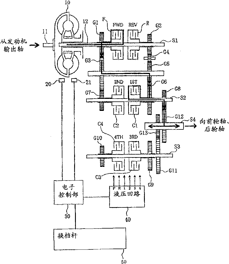
[0029] figure 1 The illustrated clutch control device 100 is a device that hydraulically controls the hydraulic clutches C1 to C4 incorporated in the transmission 110 . The transmission 110 has, as its basic components, a torque converter 10, clutch shafts S1 to S3, an output shaft S4, a plurality of gears G1 to G13, a forward hydraulic clutch F, a reverse hydraulic clutch R, and 1st to 4th gears. Used hydraulic clutches C1~C4.
[00...
no. 2 approach
[0057] Below, refer to Figure 6 and Figure 7 A clutch control device 100 according to a second embodiment of the present invention will be described.
[0058] In the clutch control device 100 of the second embodiment, as the engine speed for determining the above-mentioned combination control information S, instead of using the shift start time, a predicted speed a little time after the shift start time is used. Other configurations are the same as those of the above-mentioned first embodiment. The differences from the first embodiment will be mainly described below.
[0059] Figure 6 It shows the change of the engine speed with time before and after the start of the shift, and the vertical axis is the rotational speed, and the horizontal axis is the time axis. in addition, Figure 6 This indicates that the change in the engine speed during gear shifting is larger than usual. Such a large change in the engine rotational speed occurs, for example, when the accelerator pe...
no. 3 approach
[0072] Next, a clutch control device according to a third embodiment of the present invention will be described.
[0073] The clutch control device according to the third embodiment is installed in a construction vehicle (for example, a wheel loader) capable of automatic mode setting for automatically selecting a speed level according to conditions such as vehicle speed and engine speed.
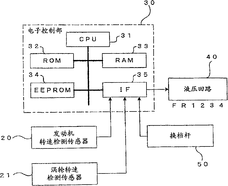
[0074] Figure 8 A block diagram showing the electrical configuration of the clutch control device of the third embodiment is shown in . The automatic mode includes a driving mode suitable for construction vehicles and a working mode suitable for bucket operations, etc., and can be switched and selected by operating the mode switching switch 60 . An operation signal from the mode selector switch 60 operated by the operator is input to the electronic control unit 30 a of the clutch control device through the interface 35 .
[0075] In the RRPROM 34a of the electronic control unit 30, combin...
PUM
 Abstract
Description
Claims
Application Information