
Crescent lock

A technology of a crescent lock and a lock cylinder is applied in the field of crescent locks, which can solve the problems of easy picking up of cam locks and poor safety, and achieve the effects of increasing safety and security, simple structure and low cost.

Inactive Publication Date: 2008-04-30
联程机械(宁波)有限公司
View PDF0 Cites 2 Cited by
  • Summary
  • Abstract
  • Description
  • Claims
  • Application Information

AI Technical Summary

Problems solved by technology

For some single-function window locks, such as a cam lock installed between two windows, as long as the cam lock disc shaft in the cam lock is connected to the frame of one window, the catch in the cam lock is fixedly arranged on the other side. On the corresponding frame of the window, turn the cam lock disc to slide into the lock, and then the window can be locked. Although the structure of this cam lock is relatively simple, because the cam lock disc is relatively easy to rotate, it can be locked between two windows. When there is a gap, the cam lock is easier to be picked open, and the security is not good

Method used


Image

  • Crescent lock
  • Crescent lock

Examples


Embodiment 1

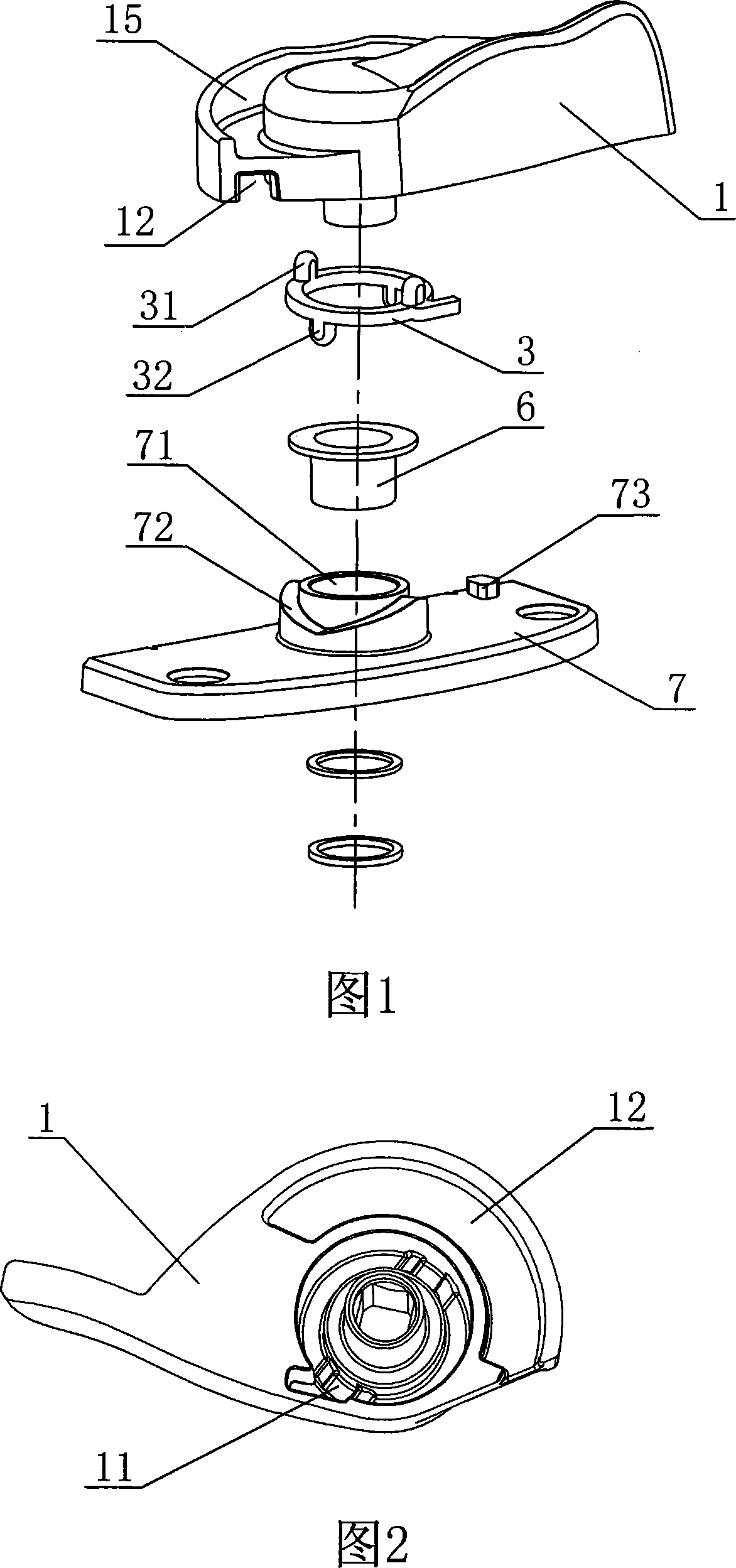
[0017] Embodiment 1: As shown in the figure, a crescent lock includes a base 7, a spring coupling 3 and a cam lock disc 1, and the cam lock disc 1 is provided with a lock catch fixedly arranged on the window frame (in the figure Not shown) the chute 15 for sliding fit, the base 7 is integrally provided with a shaft seat 71 and a chute seat 72, the chute seat 72 is coaxially arranged outside the shaft seat 71, and the cam lock disc 1 is provided with a positioning groove 11 , the upper end surface and the lower end surface of the spring coupling 3 are respectively integrally provided with a first positioning protrusion 31 and a second positioning protrusion 32, the first positioning protrusion 31 is clamped in the positioning groove 11, and the second positioning protrusion The block 32 is slidably matched with the chute seat 72, the cam lock disc 1 is connected to the shaft seat 71, and the coaxial sleeve between the cam lock disc 1 and the shaft seat 71 is provided with a bush...

Embodiment 2

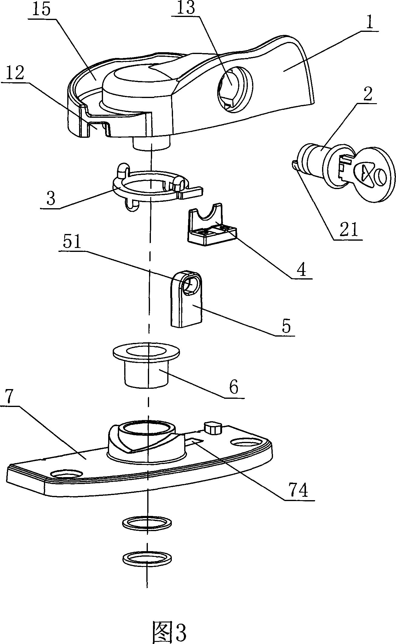
[0018] Embodiment 2: As shown in the figure, other structures are the same as Embodiment 1, the difference is that a lock cylinder hole 13 and a lock cylinder fixing frame 4 are added on the cam lock plate 1, and the lock cylinder 2 penetrates into the lock cylinder hole 13 and Fixed by the lock core holder 4, the front end of the lock core 2 is integrally provided with an eccentric lock pin 21, and one end of the dead bolt 5 is provided with a lock pin hole 51, the width of the lock pin hole 51 is greater than the height of the lock pin hole 51, and the lock pin 21 extends into the lock pin hole 51, the base 7 is provided with a lock tongue hole 74, and the other end of the lock tongue 5 is slidingly fitted with the lock tongue hole 74.


PUM


Abstract

The invention discloses a crescent lock, which comprises a base and a cam lock disk matched with a lock catch fixed and arranged on a window frame. An axle seat is integrally arranged on the base, and the cam lock disk is coupled on the axle seat. The invention is characterized in that an elastic positioning device is arranged between the cam lock disk and the base; the invention has the advantages that the structure is simple, the cost is low, because the elastic positioning device is arranged between the cam lock disk and the base, and the relative rotation between the cam lock disk and the base requires a certain external force, when the window is closed, even through a gap exists between two window casements, the window lock is uneasily to be picked; a lock disk locking mechanism is additionally arranged between the cam lock disk and the base, the cam lock disk is locked on the base through a lock core and a dead bolt, and the mutual rotation between the cam lock disk and the base can not happen, thereby greatly increasing the safety and the insurance of the window lock.

Description

technical field [0001] The invention relates to a lock, in particular to a crescent lock. Background technique [0002] Window is an integral part requisite in house construction, and for anti-theft, people have installed window lock on window, and for this reason, various window locks are full of beautiful things in the market at present. For some single-function window locks, such as a cam lock installed between two windows, as long as the cam lock disc shaft in the cam lock is connected to the frame of one window, the catch in the cam lock is fixedly arranged on the other side. On the corresponding frame of the window, turn the cam lock disc to slide into the lock, and then the window can be locked. Although the structure of this cam lock is relatively simple, because the cam lock disc is relatively easy to rotate, it can be locked between two windows. When there is a gap, the cam lock is easy to be picked open, and the security is not good. Contents of the invention ...

Claims


Application Information

Patent Timeline
Patent Type & Authority Applications(China)
IPC IPC(8): E05C3/10
Inventor 庄子平
Owner 联程机械(宁波)有限公司
Learn More