Anti-theft escape window

An anti-theft window and escape window technology is applied in the field of anti-theft escape windows, which can solve the problems that the window cannot be fully closed, the anti-theft performance is poor, and the key is easy to lose, and achieves the effects of strong perception, beautiful appearance and good anti-theft performance.

Active Publication Date: 2018-06-29
陈统平
View PDF6 Cites 0 Cited by
  • Summary
  • Abstract
  • Description
  • Claims
  • Application Information

AI Technical Summary

Problems solved by technology

[0002] At present, the windows of general residential buildings are mostly equipped with mesh structures formed by welding metal mesh or metal strips to prevent outsiders from entering the room through the windows. However, according to fire regulations, at least one window in each suite is required to be incomplete Closed, in an emergency, personnel can enter and exit through the partially closed window. For this reason, most of the partially closed windows use one side of the window to be hinged on the window frame, and the other side is provided with a locking nose, and the window is locked by a padlock. The body is locked with the window frame, and its disadvantages are: first, because the incompletely closed window is not used all the year round, it is easy to cause the lock head of the padlock to rust due to rain, moisture, etc., and it cannot be opened to escape in an emergency; Since the incompletely closed windows are not used all year round after being locked, the key to unlock the lock is also easy to lose. In an emergency, the key cannot be found, and it is also difficult to escape; third, even if the window can be opened in time, if the indoor fire or smoke is too large, wait indoors Rescue will also cause injuries to adults; the fourth is that the appearance of the anti-theft window opened and closed by the padlock is not beautiful enough, and the padlock is easy to be picked open, and its anti-theft performance is poor.

Method used


Image

  • Anti-theft escape window
  • Anti-theft escape window
  • Anti-theft escape window

Examples


Embodiment Construction

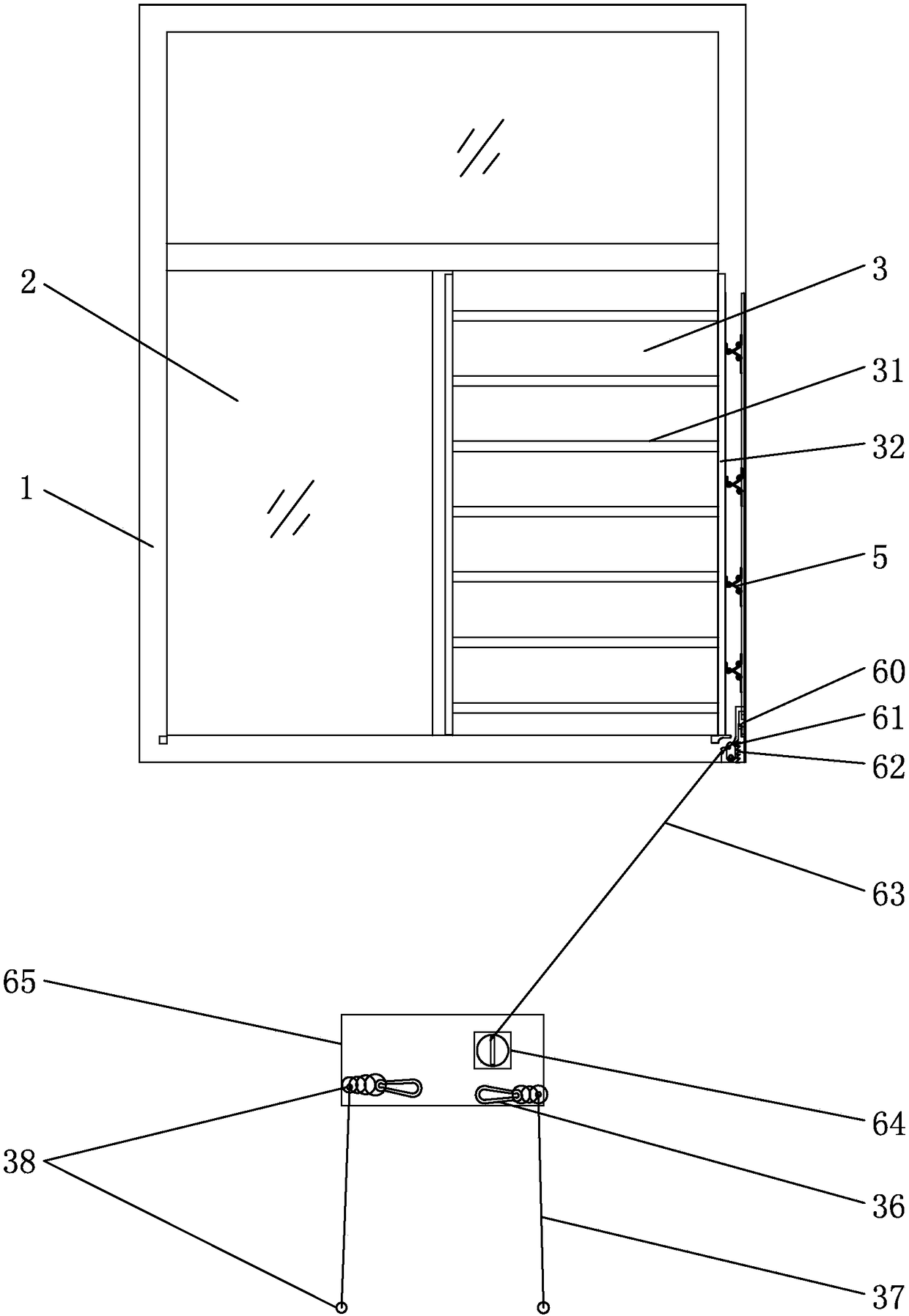
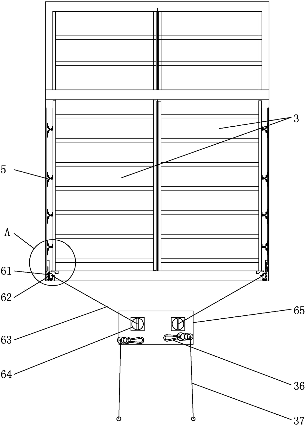
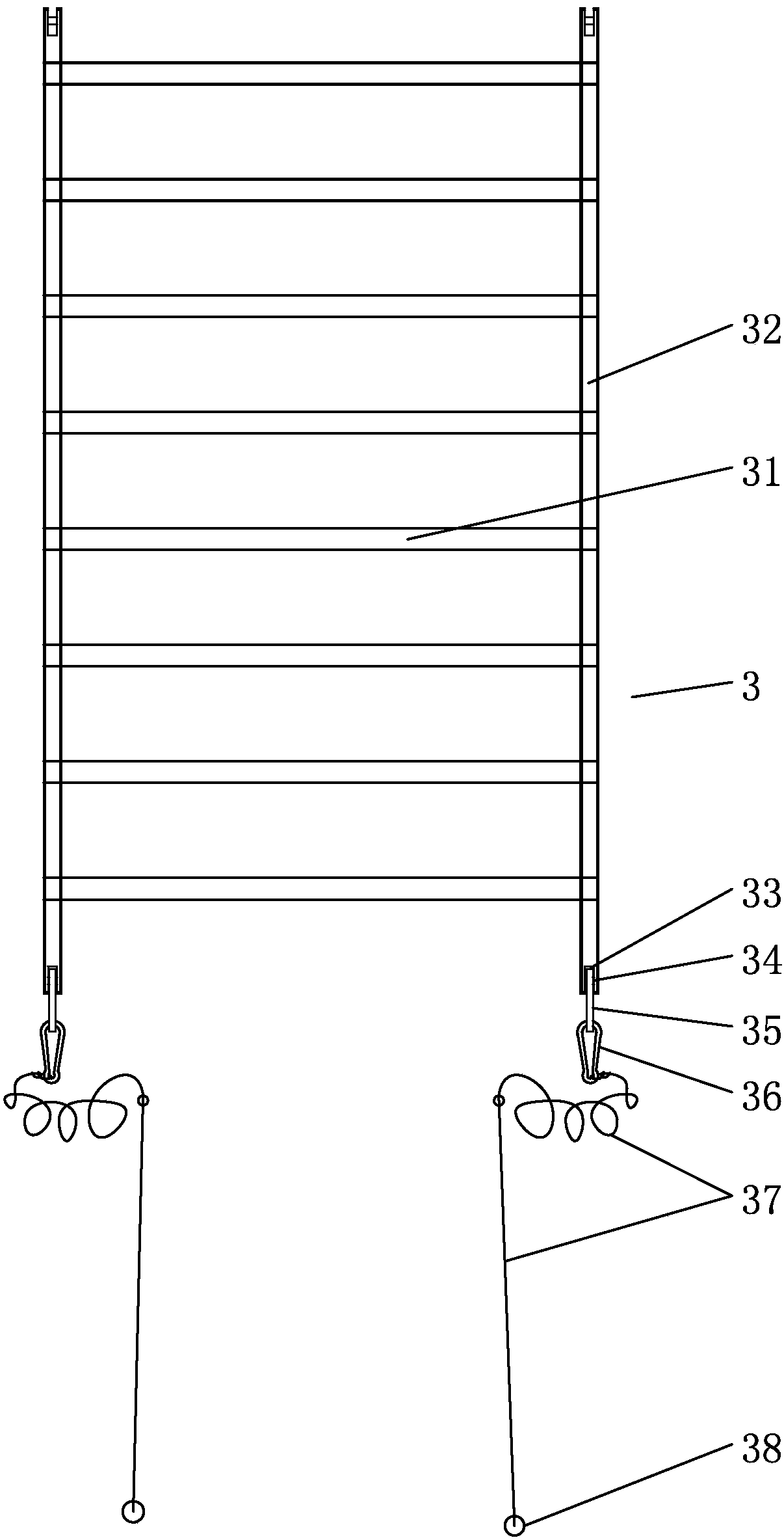
[0030] Below in conjunction with accompanying drawing, the present invention will be further described with specific embodiment, see Figure 1-Figure 9 :

[0031] The anti-theft escape window includes a window frame and an anti-theft window 3 installed on the window frame. The anti-theft window 3 is welded and connected with two or more horizontal bars 31 arranged at intervals between two vertical bars 32 parallel to each other, forming Ladder-shaped anti-theft window 3, the window frame is provided with vertical grooves 73 on the opposite sides of two vertical frames 70, a slide frame 71 is fixedly installed on the bottom of a vertical groove 73, and the front side of the slide frame 71 A vertical trapezoidal chute 74 is provided, and a pull rod 72 is slid in the chute 74. Restricted by the trapezoidal chute 74, the pull rod 72 can only move axially in the chute 74. The side walls of the chute 74 and The pull rod 72 is provided with more than one group of telescopic frames 5...


PUM


Abstract

The invention belongs to the technical field of antitheft windows, and relates to an antitheft escape window. The antitheft escape window comprises a window frame and an antitheft window body mounted on the window frame. According to the antitheft window body, more than two cross bars arranged at intervals are welded and connected between two parallel vertical rods. According to the window frame, vertical grooves are formed in opposite side faces of two vertical frames, a vertical sliding groove is formed in the bottom of one of the vertical grooves, a pull rod is arranged in the sliding groove, and expansion brackets, which are controlled by the pull rod to eject or separate from the vertical rods of the antitheft window body on the same side, are arranged on the side walls of the sliding groove and the pull rod at intervals. A rack is connected to the lower portion of the pull rod, a pawl, which is clamped to the rack when being located at the ejection position of the expansion bracket at the vertical rods, is hinged to the window frame, and a reset spring and a pull rope for pulling the pawl to separate from the rack are connected to the pawl. The antitheft escape window has the advantages of attractive appearance, high antitheft performance, easiness in opening, capability of enabling indoor persons to climb out of the window and climb thereon for waiting rescue or directly climb down to the ground and applicability to various building windows in need of antitheft window mounting.

Description

technical field [0001] The invention belongs to the technical field of anti-theft windows, in particular to an anti-theft escape window. Background technique [0002] At present, the windows of general residential buildings are mostly equipped with mesh structures formed by welding metal mesh or metal strips to prevent outsiders from entering the room through the windows. However, according to fire regulations, at least one window in each suite is required to be incomplete Closed, in an emergency, personnel can enter and exit through the partially closed window. For this reason, most of the partially closed windows use one side of the window to be hinged on the window frame, and the other side is provided with a locking nose, and the window is locked by a padlock. The body is locked with the window frame, and its disadvantages are: first, because the incompletely closed window is not used all the year round, it is easy to cause the lock head of the padlock to rust due to rai...

Claims


Application Information

Patent Timeline
Patent Type & Authority Patents(China)
IPC IPC(8): E06B9/06E06C1/34
CPCE06B9/06E06C1/34
Inventor 陈明松陈统平
Owner 陈统平
Why Eureka
Try Eureka