Light source drive circuit

A technology of light source driving circuit and dimming circuit, which is applied in the direction of light source, electric light source, electric lamp circuit layout, etc., can solve the problems of 107 breakdown of the dimming circuit, reducing product competitiveness, increasing the overall circuit volume, etc.

Inactive Publication Date: 2008-04-30
CPT TECH GRP
View PDF0 Cites 21 Cited by
  • Summary
  • Abstract
  • Description
  • Claims
  • Application Information

AI Technical Summary

Problems solved by technology

[0007] In this case, if the withstand voltage of the dimming circuit 107 is insufficient, the dimming circuit 107 will be broken down by the DC power voltage supplied by the DC-to-DC power converter 103, resulting in damage to the dimming circuit 107.
In addition, it may be necessary to use a dimming circuit 107 with a hi

Method used


Image

  • Light source drive circuit
  • Light source drive circuit
  • Light source drive circuit

Examples


Embodiment Construction

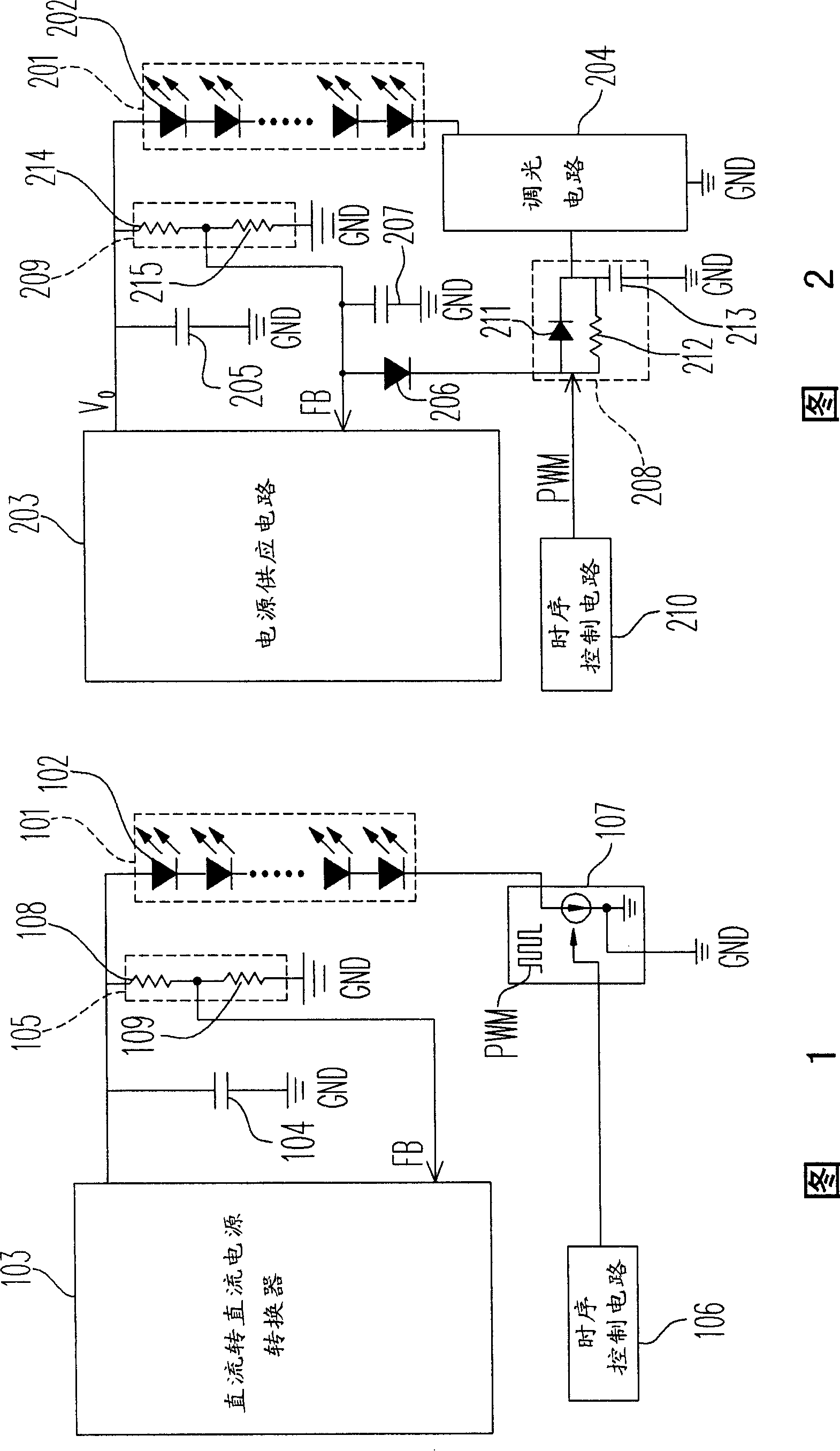
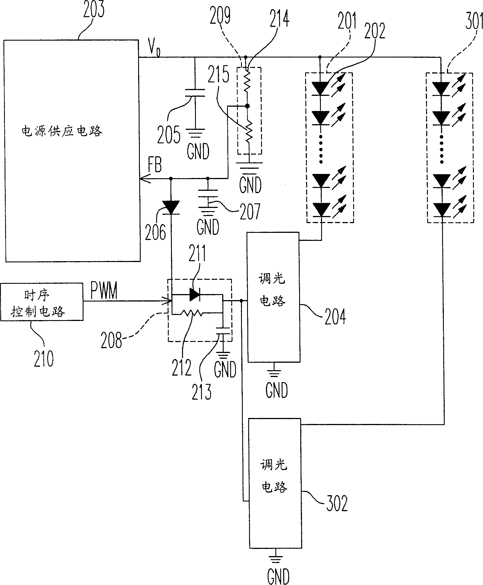
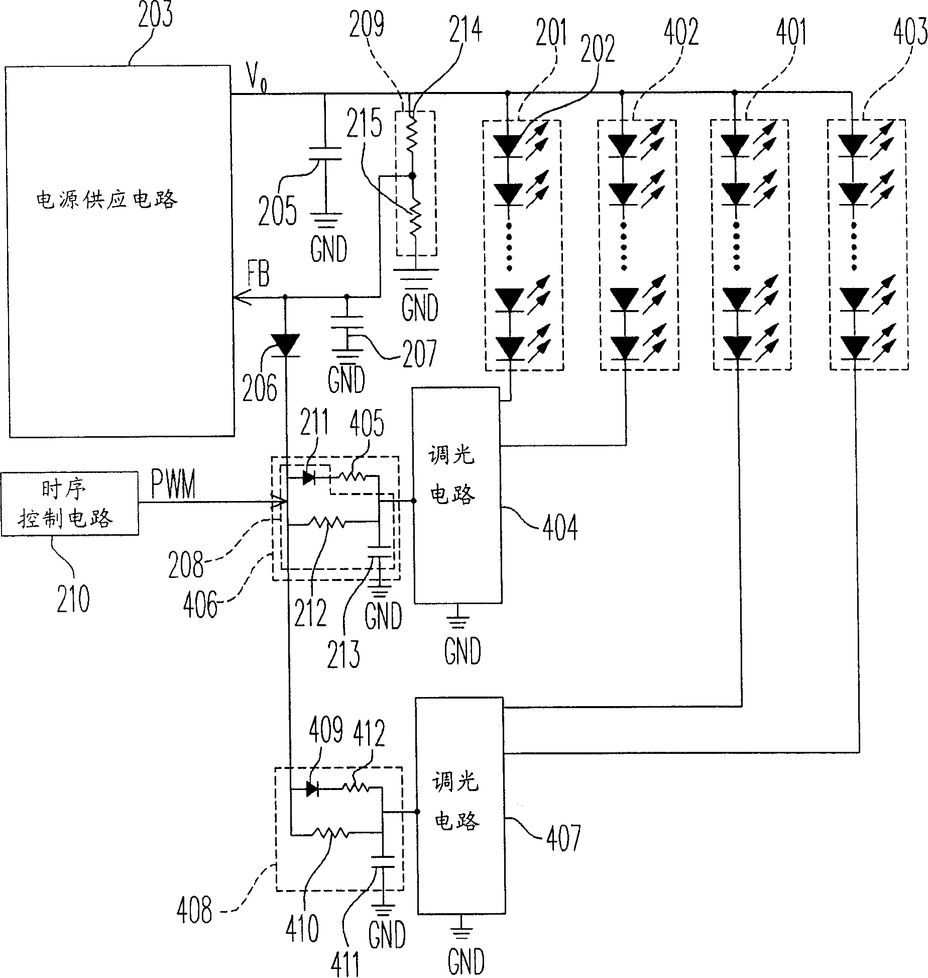
[0065] FIG. 2 is a circuit diagram of a light source driving circuit according to an embodiment of the invention. Please refer to FIG. 2 , the light source driving circuit is used to drive the first light emitting element 201 . The first light-emitting element 201 may be a light-emitting diode, as shown in 202 in FIG. 2 , or may be a light-emitting diode string formed by connecting a plurality of light-emitting diodes 202 in series, or other types of light-emitting elements / light-emitting element strings. The light source driving circuit includes a power supply circuit 203, a first dimming circuit 204, a capacitor 205, and a feedback circuit.

[0066] The power supply circuit 203 has an output terminal and a feedback terminal, and the output terminal is coupled to one end of the first light-emitting element 201 for supplying the power supply voltage Vo to the first light-emitting element 201, and the power supply circuit 203 is configured according to the feedback terminal. T...


PUM


Abstract

A light source driving circuit for driving a light emitting element comprises a power supply circuit, a light adjusting circuit, and a feedback circuit/control circuit, wherein the power supply circuit is coupled with one end of a light emitting element; the light adjusting circuit is coupled with the other end of the light emitting element; and the feedback circuit/control circuit is coupled between the power supply circuit and the light adjusting circuit. When the light source drive circuit turns off the power supply circuit to stop supplying power to the light emitting element, the feedbackcircuit/control circuit delays the time point for switching off the light adjusting circuit so as to prevent the light adjusting circuit from being broken down by over-high voltage.

Description

technical field [0001] The present invention relates to a driving circuit, and in particular to a light source driving circuit for driving light-emitting elements. Background technique [0002] Light source driving circuits are widely used in various display devices, such as backlight driving circuits of liquid crystal displays, or light emitting diode (LED) driving circuits of handheld mobile devices. As display devices are increasingly used in various electronic products, the light source driving circuit has high development potential. There are many advantages that can be continuously improved and improved, including increased power conversion efficiency, improved stability, and so on. [0003] The structure of a known light source driving circuit for driving a LED string 101 is shown in FIG. 1 , wherein the LED string 101 is composed of a plurality of LEDs 102 connected in series. This known light source driving circuit includes a DC-to-DC power converter 103 , a capac...

Claims


Application Information

Patent Timeline
IPC IPC(8): G09G3/34G09G3/36G09G3/20H05B37/02G02F1/133
CPCY02B20/42Y02B20/40
Inventor 陈弼先赵翰楀林信彰
Owner CPT TECH GRP
Why Eureka
Try Eureka