
Method and device for transferring a pattern from a stamp to a substrate

A technology of stamp and substrate, which is applied in the field of transferring patterns from stamp to substrate and device, can solve the problems of deformation of transfer pattern and unsatisfactory device, etc.

Active Publication Date: 2008-04-30
KONINKLIJKE PHILIPS ELECTRONICS NV
View PDF2 Cites 19 Cited by
  • Summary
  • Abstract
  • Description
  • Claims
  • Application Information

AI Technical Summary

Problems solved by technology

However, this device is not satisfactory when higher precision is required
It appears that switching the valve from vacuum to overpressure causes vibration, causing distortion of the transfer pattern

Method used


Image

  • Method and device for transferring a pattern from a stamp to a substrate
  • Method and device for transferring a pattern from a stamp to a substrate

Examples


Embodiment Construction

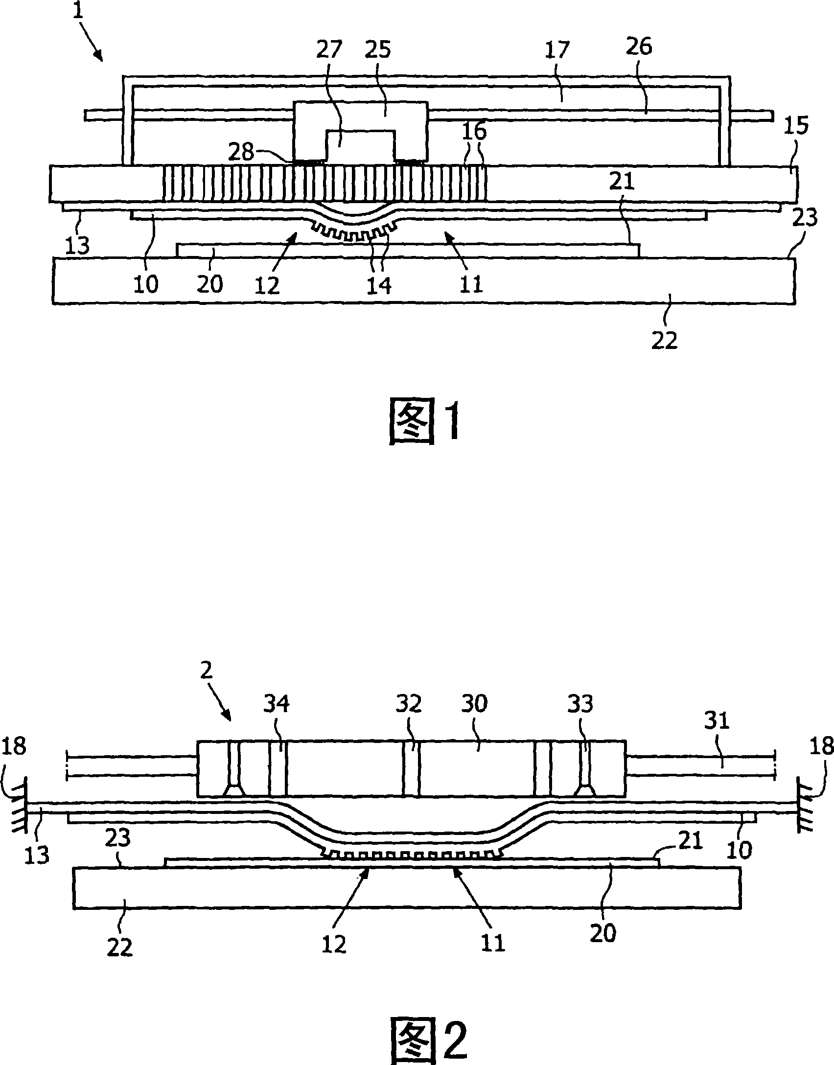
[0029] FIG. 1 schematically shows a device according to a first embodiment, denoted by the reference symbol 1 . This device 1 is referred to as a first pattern transfer device 1 below.

[0030] The first pattern transfer device 1 is used to transfer the pattern 12 from the embossing surface 11 of the stamp 10 to the receiving surface 21 of the substrate 20 . To support the substrate 20 , the first pattern transfer device 1 comprises a table 22 with a support surface 23 . The base body 20 is fixed on a stage 22 by a suitable fixing mechanism (not shown). For example, the table 22 can be designed as a vacuum chuck, which holds the base body 20 on the support surface 23 by means of a vacuum.

[0031] The stamp 10 is made of a flexible material so that it is very easy to deform the stamp 10 . For example, the material of the stamp 10 is chosen such that local deformations already occur when a small portion of the stamp 10 is subjected to a very slight overpressure of only 1 kPa...


PUM


Abstract

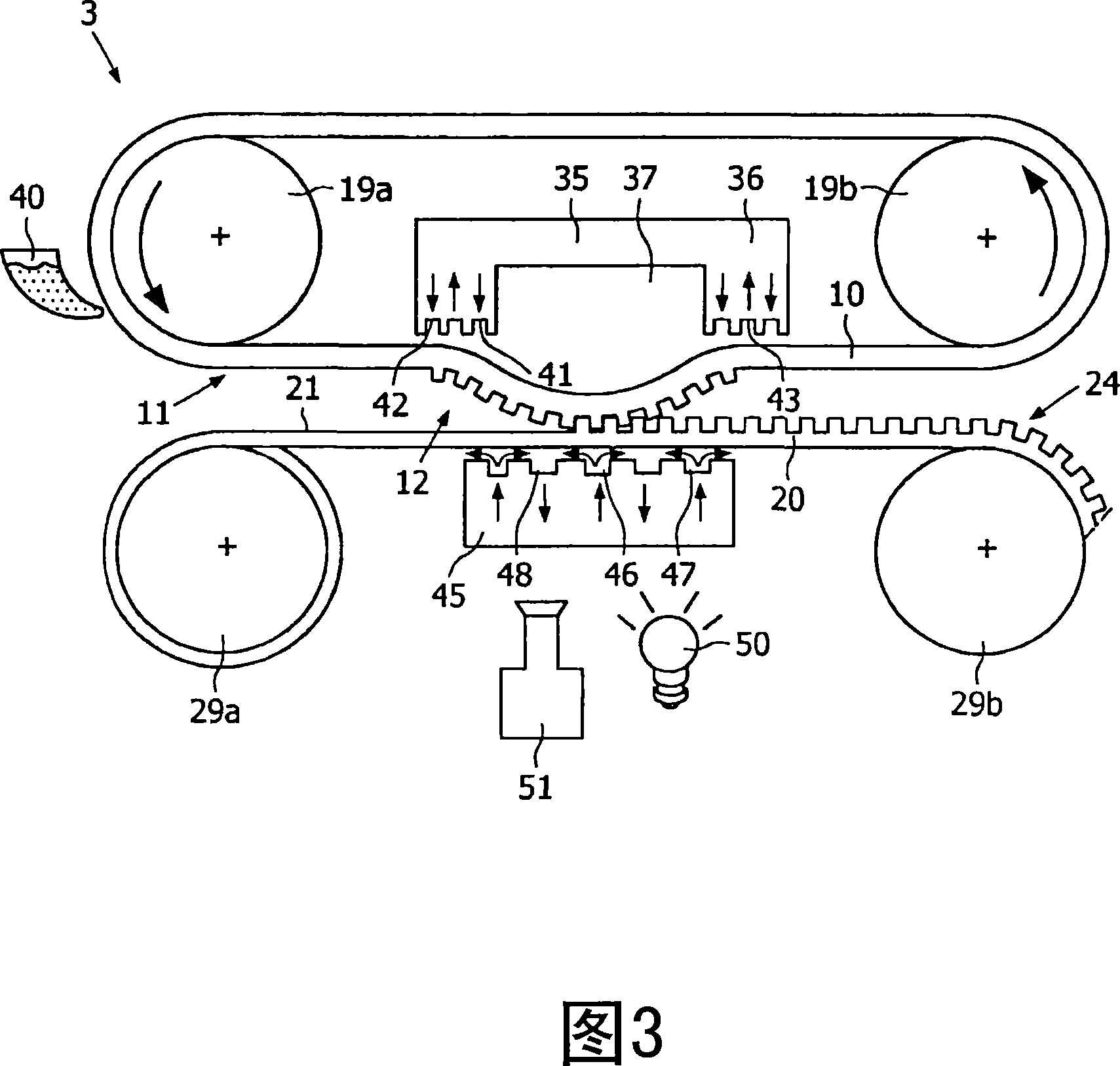
A device (1) for transferring a pattern (12) from a stamp (10) to a substrate (20) comprising a table (22) supporting the substrate (20), a flexible stamp (10) and a movably arranged body (25), the body (25) has a pressure chamber (27) that applies pressure to a part of the stamp (10), thereby pushing this part towards the substrate (20) and into contact with the substrate (20). During pattern transfer, the body (25) is moved. As a result, adjacent parts of the stamp (10) are continuously pushed towards the substrate (20), contacting the substrate (20) and moved back into position again. In this way, the transfer of the pattern (12) of the stamp (10) to the substrate (20) is achieved without causing vibrations, thereby achieving the transfer of the pattern (12) in a high-precision manner.

Description

technical field [0001] The invention relates to a method of transferring a pattern from an embossing side of a stamp to a receiving surface of a substrate, wherein at least one of the embossing and receiving faces is flexible and the stamp partially transfers the pattern to the substrate The continuous transfer zone is formed over a period of time and subsequently canceled. [0002] This method is particularly suitable for use in the field of microcontact printing, which is considered a printable electronics actuation technology. In microcontact printing, the pattern features that are transferred are in the micron and submicron range. In particular, the pattern includes microstructures with raised portions. Background technique [0003] Typically, inks comprising so-called thiol molecules are used in microcontact printing. Initially, the stamp is saturated with these molecules by dipping the stamp in a solution, thereby causing the stamp to absorb these molecules. When t...

Claims


Application Information

Patent Timeline
Patent Type & Authority Applications(China)
IPC IPC(8): B41K3/04B41K3/36B41K1/02B41M1/40G03F7/00B05D1/42
CPCB82Y10/00B41K3/36G03F7/0002B41K3/12B05D1/28B82Y40/00B41K3/02B81C1/0046
Inventor R·M·施奈德M·J·J·多纳M·M·J·德克雷
Owner KONINKLIJKE PHILIPS ELECTRONICS NV
Learn More