
Support bearing assembly

一种轴承组件、支撑件的技术,应用在轴承、轴和轴承、滚动接触轴承等方向,能够解决任何用户不合适、军事用户存在潜在危险、天线杆损害等问题

Inactive Publication Date: 2008-05-07
AMERICAN WB CO
View PDF0 Cites 9 Cited by
  • Summary
  • Abstract
  • Description
  • Claims
  • Application Information

AI Technical Summary

Problems solved by technology

The described setup does not provide sufficient support to the screw, allowing the screw to wobble during operation and potentially damaging the mast
This single bearing scheme is also only fully at low speeds and would be unsuitable for any user and potentially dangerous for emergency or military users

Method used


Image

  • Support bearing assembly
  • Support bearing assembly
  • Support bearing assembly

Examples


Embodiment Construction

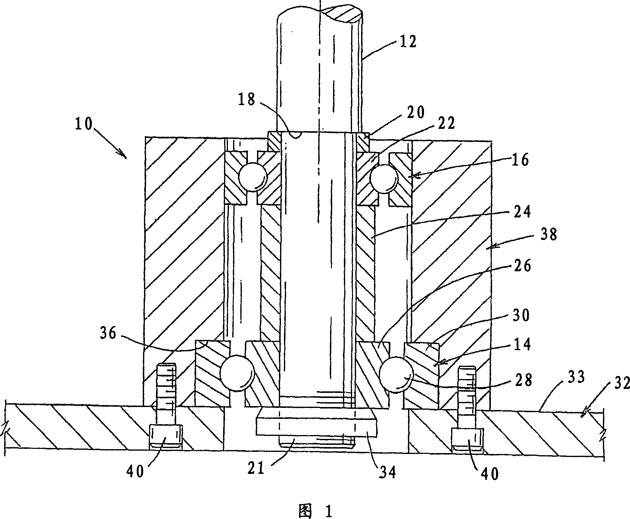
[0029] Referring to FIG. 1 , a prior art rigid bearing assembly 10 around an axis of rotation 12 is shown. The axis of rotation is shown as an axial drive screw of a screw driven telescoping antenna mast assembly, but is not limited thereto. A bearing assembly allows the shaft to rotate freely. Bearings 14 and 16 are positioned axially along the length of the shaft to provide lateral support to the rotating shaft. The axial spacing of the bearings provides moment resistance against tipping of the shaft. Vertical support in the downward direction is provided by the lower shoulder 18 of the shaft which will force through the washer 20, the inner race 22 of the upper bearing 16, the bushing 24, the inner race 26 of the lower bearing 14, the lower The ball bearings 28 of the bearings, and the outer ring 30 of the lower bearing 14 are transferred to the upper surface 33 of the base 32 . Vertical support in the upward direction is provided by lifting the shaft on a lock nut or "h...


PUM


Abstract

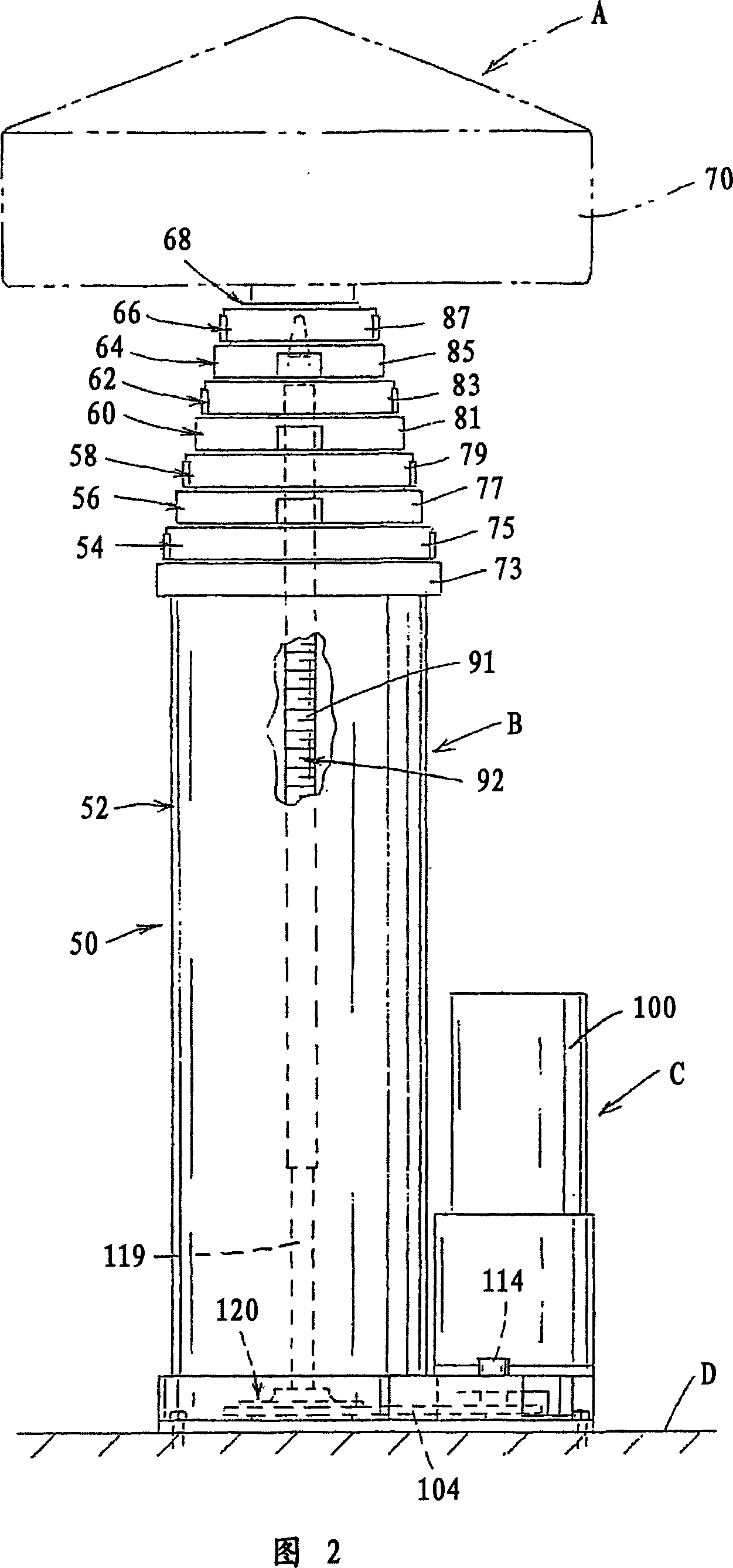
The present invention relates to a rigid support bearing for a rotating shaft has bearings arranged concentrically around the shaft instead of spaced axially and is used in a screw drive telescoping mast assembly. An axial drive screw is centrally located in the mast assembly for extending and retracting the tubular sections. A lower bearing assembly supports the drive screw and uses the concentric bearing arrangement to reduce the nested height of the mast.

Description

[0001] priority claim [0002] This application claims priority to Provisional Application No. 60 / 660,805, filed March 11, 2005, which priority application is incorporated herein by reference. technical field [0003] The invention relates to rigid supports for rotating shafts. More specifically, the invention relates to the use of a rigid support for one end of an axially driven screw in a screw driven telescoping antenna mast. Background technique [0004] The present invention is applicable to screw driven telescoping antenna masts and will be described with particular reference to said telescoping masts, however, the present invention has broader application and can be used in a variety of other applications where a rigid bearing assembly for a rotating shaft is required. used in the application. [0005] Two important criteria for telescoping masts are the "nested" or fully retracted height and the "deployed" or fully extended height. The nested height is the height ...

Claims


Application Information

Patent Timeline
Patent Type & Authority Applications(China)
IPC IPC(8): F16B7/00
CPCF16C2300/34F16C19/54E04H12/182
Inventor 保罗·布拉德福德·布莱克韦尔德
Owner AMERICAN WB CO
Learn More