Lens fixing mechanism for part frame spectacle
A technology for fixing lenses and glasses, which is applied in the directions of glasses/protective glasses, glasses/goggles, lens components, etc., which can solve the problems of inconvenience and achieve the effect of simple insertion and removal
- Summary
- Abstract
- Description
- Claims
- Application Information
AI Technical Summary
Problems solved by technology
Method used
Image

Examples
Embodiment 1
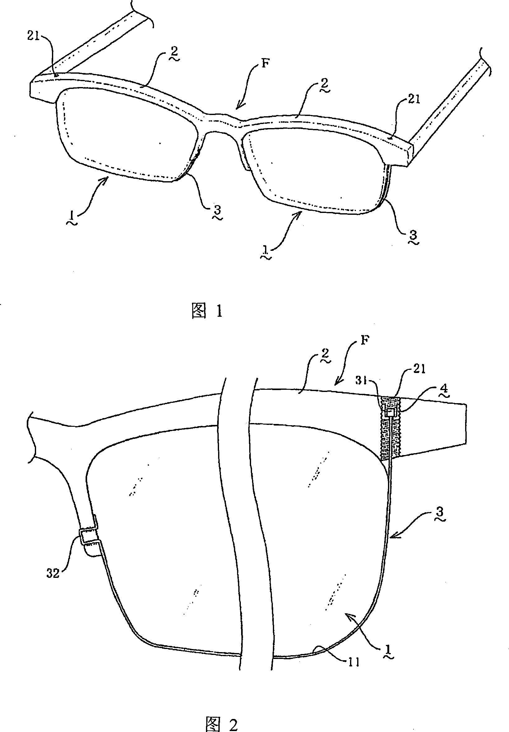
[0025] Referring to Figures 1 to 3, 1 is a lens, 2 is a frame rod, 3 is a fixed wire, and 4 is a tubular screw. In this embodiment, zinc-nickel-nickel copper is used to make the upper chord portion supported by the arc-shaped frame rod 2 on the outer periphery of the lens 1. The metal front frame F (see Figure 1).
[0026] Fasten the fixed line 3 that is not fixed by the frame bar 2 on the outer periphery of the remaining lens to adopt strong and tough stainless steel wire, and one end of the fixed line 3 is spot-welded with a cylindrical member to form a cylindrical anti-off block 31 (see Figure 2).
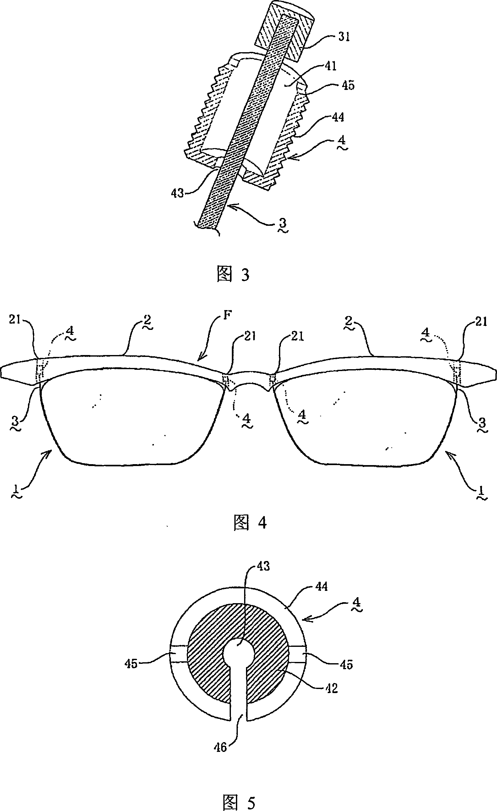
[0027] At the arc end on the temple side of the frame rod 2, an internal thread cylinder portion 21 that can slidably embed the anti-off block 31 is penetrated, and an inner tube portion 41 that can slidably embed the anti-off block 31 of the fixed wire 3 is provided therein. , The outer circumference of the tubular screw 4 is provided with an external thread 44 that matches the...
Embodiment 2
[0033] Referring to Fig. 4 and Fig. 5, it is the same as Embodiment 1, except that in this embodiment, the plastic front frame F is made of cellulose acetate resin, and at the same time, anti-off blocks 31 are formed at both ends of the fixing line 3 , and the two arc ends of the glasses bridge side and the temple side of the frame rod 2 are respectively provided with internally threaded holes 21 (see FIG. 4 ) for inserting the anti-off block 31 . The fixed wire 3 is a nylon cord, and the end of the cord is melt-molded to form a stopper 31 . Even if the fixed wire 3 is made of a synthetic fiber single-ply cord, since the fixed wire 3 is inserted while adjusting the tension force by screwing in and out of the tubular screw 4, there is no need to worry about the fixing wire 3 being broken due to excessive stretching. Case. In this embodiment, the tubular screw 4 is provided with a linear slit 46 from the opening to the fixing wire hole 43, by means of which, the fixing wire 3 i...
Embodiment 3
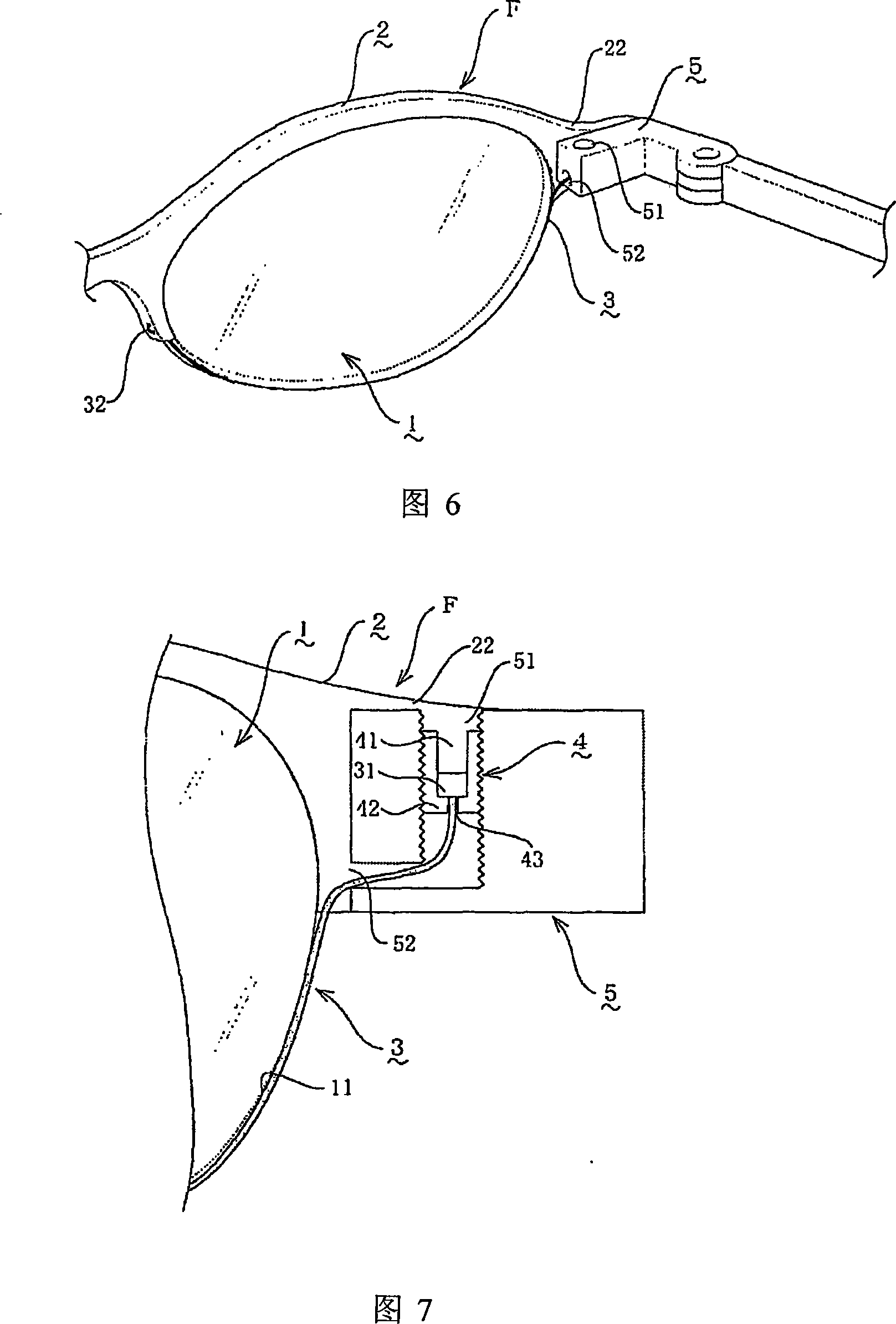
[0035] Referring to Fig. 6 and Fig. 7, it is the same as Embodiment 1, except that in this embodiment, an extension 22 is formed on the arc end of the temple bar 2 on the side of the temple, and at the same time behind the extension 22 A connecting portion 5 is provided on the upper portion, and an internal threaded cylindrical portion 51 (see FIG. 6 ) that is slidably embedded in the anti-off block 31 is provided through the upper surface of the connecting portion 5 .
[0036]And from the lens side surface of the connecting part 5, there is a communicating hole 52 communicated with the internal thread cylinder part 51 of the connecting part 5, and the connection hole 52 drawn from the fixing thread hole 43 of the tubular screw 4 of the internal thread cylinder part 51 is inserted. The fixing wire 3 is led out through the communication hole 52, and is wound and hung on the lens 1 (see FIG. 7 ).
[0037] In this way, the lens fixing mechanism of the present invention can be use...
PUM
 Abstract
Description
Claims
Application Information
 - R&D
- Intellectual Property
- Life Sciences
- Materials
- Tech Scout
- Unparalleled Data Quality
- Higher Quality Content
- 60% Fewer Hallucinations
Browse by: Latest US Patents, China's latest patents, Technical Efficacy Thesaurus, Application Domain, Technology Topic, Popular Technical Reports.
© 2025 PatSnap. All rights reserved.Legal|Privacy policy|Modern Slavery Act Transparency Statement|Sitemap|About US| Contact US: help@patsnap.com