Hydraulic up-down swing mechanism

A rotary mechanism, hydraulic technology, applied in the direction of mechanical equipment, fluid pressure actuation device, fluid pressure actuation system components, etc., can solve the problems of large installation space, low control precision, complex structure, etc., to ensure the angular position Accuracy, the effect of ensuring control accuracy

Inactive Publication Date: 2008-06-18
CHINA NAT HEAVY MACHINERY RES INSTCO
View PDF0 Cites 4 Cited by
  • Summary
  • Abstract
  • Description
  • Claims
  • Application Information

AI Technical Summary

Problems solved by technology

Its structure is complex, the failure rate is high, the installation space ra

Method used


Image

  • Hydraulic up-down swing mechanism
  • Hydraulic up-down swing mechanism

Examples


Embodiment Construction

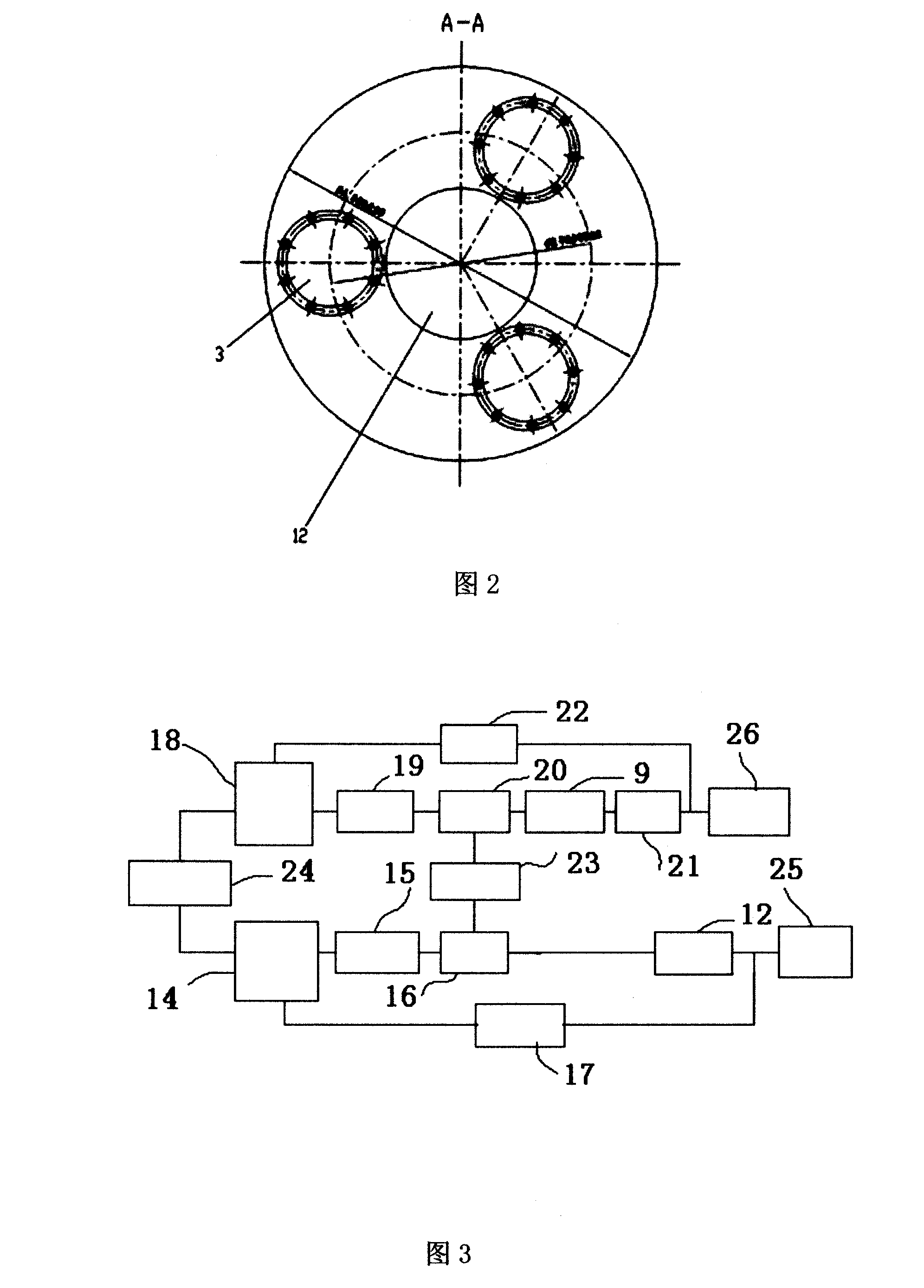
[0017] As shown in Fig. 1 and Fig. 2, there are three groups of telescopic connecting rods 3 distributed around the hydraulic cylinder 12 around the multistage single-rod double-acting multistage telescopic hydraulic cylinder 12 with an interval of 120°. The connecting rods at the end of the set of telescopic connecting rods 3 are fixed together on the load platform 1; the load platform 1 is mainly a connecting platform for load parts. The upper support guide plate 4 and the lower support guide plate 2 are sleeved up and down on the hydraulic cylinder 12 and the telescopic connecting rod 3, and the upper support guide plate 4 and the lower support guide plate 2 play a supporting and guiding role. The lifting of the hydraulic cylinder 12 will drive the telescopic connecting rod 3 and the load platform 1 to lift together.

[0018] The upper part of the three sets of telescopic connecting rods 3 has a round table or a round table with ears main support platform 5, a round table o...


PUM


Abstract

The invention belongs to the metallurgical equipment field, especially relating to a hydraulic lift-turn mechanism. The invention is characterized in that three sets of expansion connecting rods (3) are arranged around a hydraulic cylinder (12) with the interval of 120 degrees. The terminational cylinder lever of the hydraulic cylinder (12) and the terminational connecting rod of the three sets of expansion connecting rods (3) are fixed on a load platform (1). An upper support guide board (4) and a lower support guide board (2) are arranged on the hydraulic cylinder (12) and the expansion connecting rods (3). The three sets of expansion connecting rods (3) have a main support platform (5) which is connected with the hydraulic cylinder (12) by a bearing (6). A hydraulic motor (9) is fixed by a bracket (11). The output shaft end of the hydraulic motor (9) is provided with a gear, a gear pair (10) and a limit ring (7) which is fixed on the hydraulic cylinder (12) by a binding bolt. The hydraulic motor (9) rotates the gear of the output shaft end to be meshed with the gear pair (10). The invention has the advantages of good reliability, easy maintenance and operation, high control precision, strong carrying capacity and broad application range.

Description

technical field [0001] The invention belongs to the field of metallurgical equipment, and in particular relates to a hydraulic lifting and turning mechanism which can not only perform lifting (linear) movement along the vertical Z-axis, but also perform forward and reverse rotation around the Z-axis. Background technique [0002] Mechanical lifting and turning devices are widely used in many occasions that require control of stroke and angular position. At present, the mechanical lifting and turning device is mainly composed of a screw nut or a worm gear and a gear mechanism. Its structure is complex, the failure rate is high, the installation space range is large, the carrying capacity is limited, and the control accuracy is low. Contents of the invention [0003] The object of the present invention is to provide a hydraulic lifting and turning mechanism, which has small installation space, good reliability, easy maintenance, easy operation, high control precision, stron...

Claims


Application Information

Patent Timeline
IPC IPC(8): F15B15/00F15B21/02F15B13/02
Inventor 王东谷振云谢世明
Owner CHINA NAT HEAVY MACHINERY RES INSTCO
Why Eureka
Try Eureka