Display equipment of elevator

A display device and elevator technology, applied in the field of elevator display devices, can solve problems such as complex devices

Inactive Publication Date: 2008-06-18
MITSUBISHI ELECTRIC CORP
View PDF1 Cites 7 Cited by
  • Summary
  • Abstract
  • Description
  • Claims
  • Application Information

AI Technical Summary

Problems solved by technology

[0005] However, in the display device of the elevator, there is the following problem: because a plurality of floor names are continuously displayed on the circle of a predetermined shape in the above-mentioned display part, and The floor name of the current position of the passenger car and the floor name other than the current floor are displayed separately, and the above-mentioned continuous plurality of floor names are displayed on the circle of the predetermined shape in proportion to the moving speed of the above-mentioned passenger car, so the device complex

Method used


Image

  • Display equipment of elevator
  • Display equipment of elevator
  • Display equipment of elevator

Examples


Embodiment approach 1

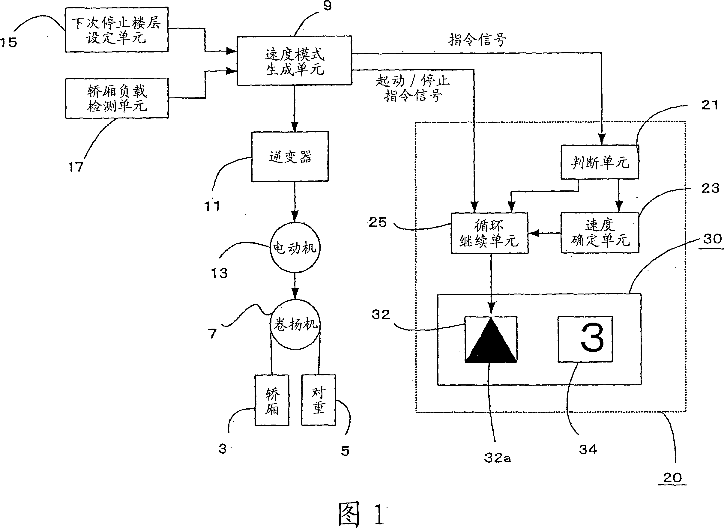
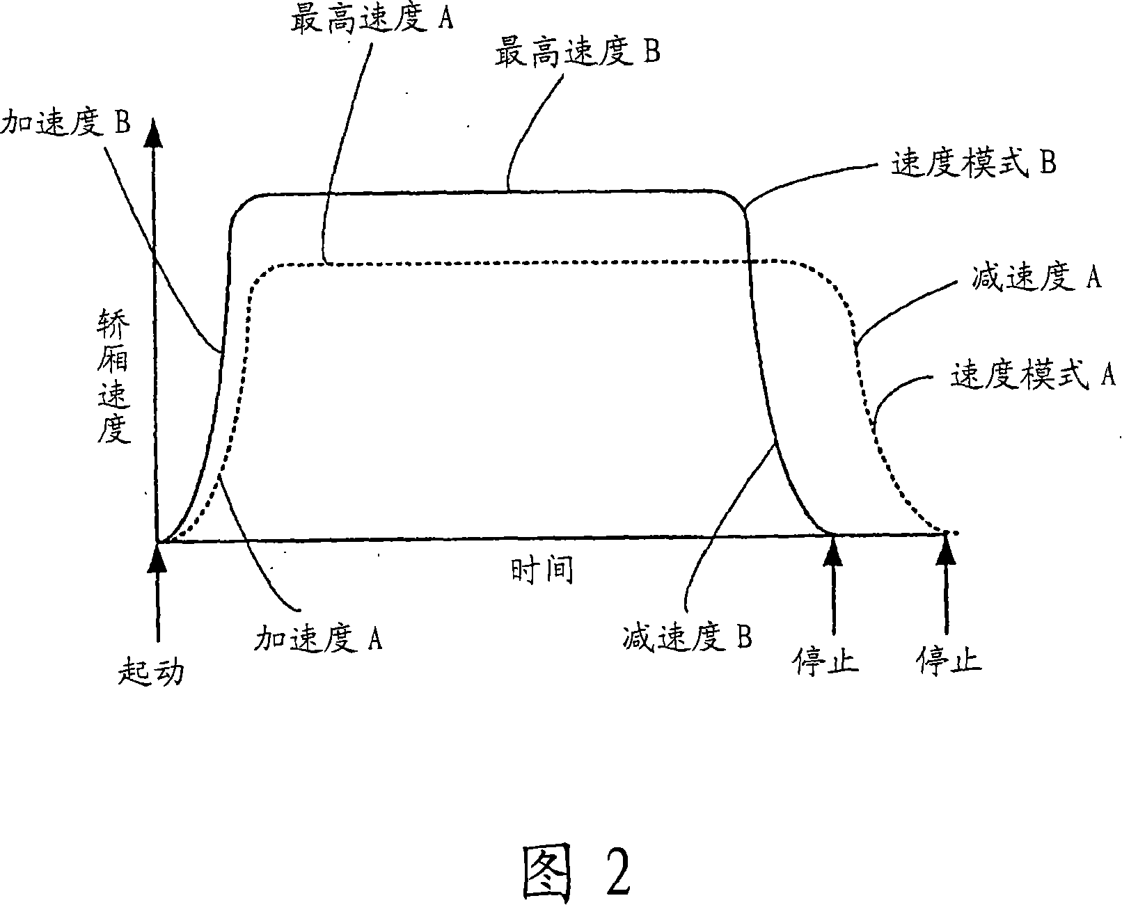
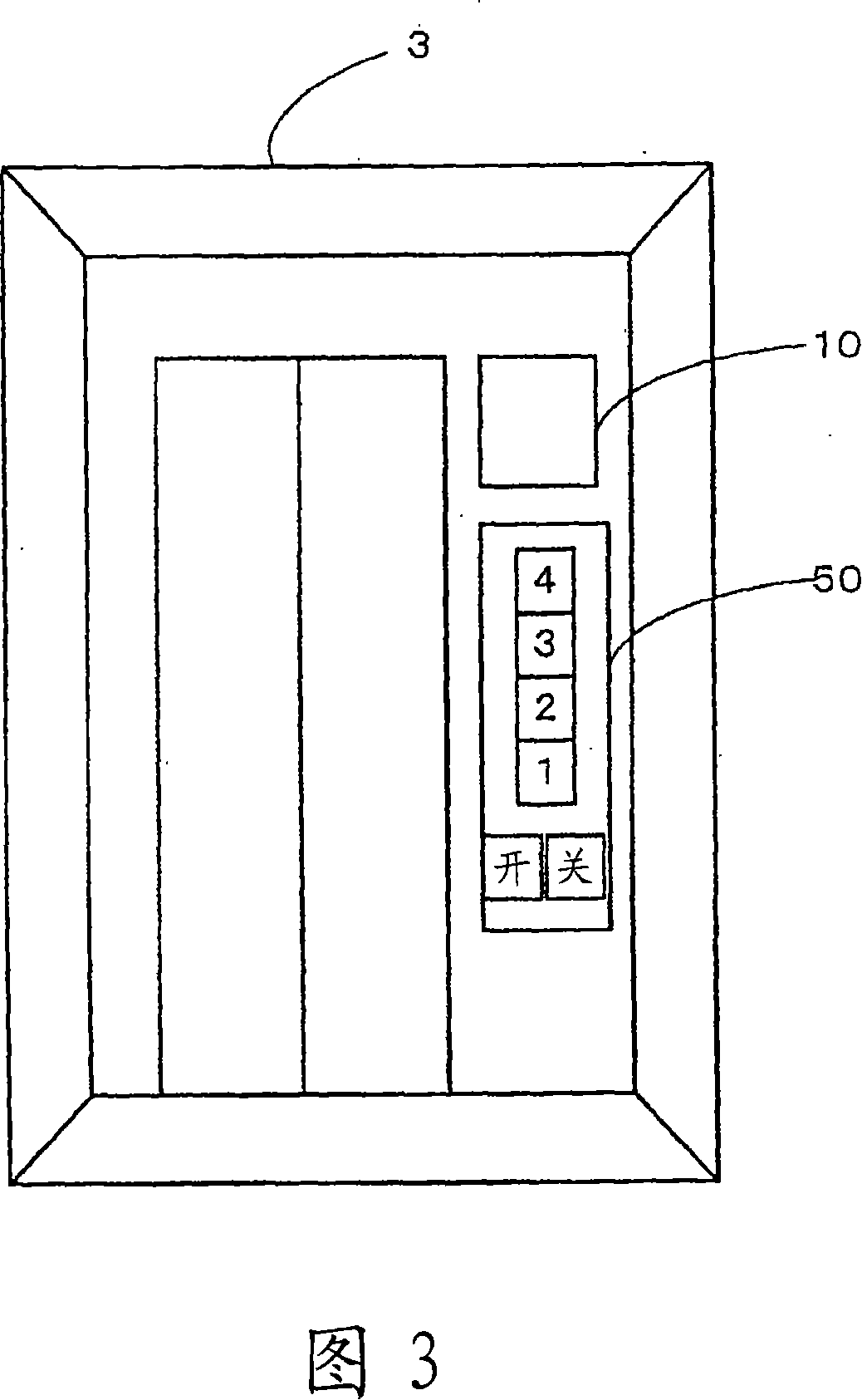
[0021] An embodiment of the present invention will be described with reference to FIGS. 1 to 4 . Fig. 1 is an overall block diagram of a display device of an elevator according to an embodiment of the present invention, Fig. 2 is a characteristic diagram of the speed of the passenger car of the elevator shown in Fig. The front view of the display device of the elevator shown in Fig. 4 is a state diagram showing the operation status of the travel sign of the display device of Fig. 1 . In FIG. 1 , an elevator has a counterweight 5 connected to a passenger car 3 via ropes, and is formed so that a hoist 7 is driven by a motor 13 powered by an inverter 11 to raise or lower the passenger car 3 .

[0022] The variable speed elevator has: a car load detection unit 17 for measuring the weight of the passenger car 3 as the car load; a next stop floor setting unit 15 for setting the next stop floor according to the car call; and The speed pattern generation unit 9 generates the allowabl...


PUM


Abstract

A display device (20) for an elevator, having speed pattern creation means (9) for creating a speed pattern by which an passenger elevator car (3) arrives at a floor of the next stop within allowable drive capacity of a motor (13) and within the shortest time. The speed pattern is created based on an elevator car load obtained by car load detection means (17) and information on a floor of the next stop set by floor-of-the-next-stop setting means (15). An inverter (11) is operated based on the speed pattern to drive the motor (13) that in turn drives a hoist (7), and the display device (20) causes, based on the speed pattern, an advance mark (32a) indicating the advance direction of the elevator car (3) to be displayed on a display section (30). The display device (20) further has circulation continuation means (25) and speed decision means (23). The circulation continuation means (25) circulates the advance mark (32a) in correspondence with the advance direction of the elevator car (3) and causes the circulation of the advance mark (32a) to continue from the start to stop of the car (3). The speed decision means (23) determines circulation speed of the advance mark (32a) based on the speed pattern and inputting a command signal for the circulation speed into the circulation continuation means (25).

Description

technical field [0001] The present invention relates to a display device for an elevator. Background technique [0002] As described in the following patent document 1, the existing elevator display device has the following parts: a speed detection device, which detects the speed of the passenger car, and outputs a speed detection signal; a position detection device, which detects the position of the passenger car, and output a position detection signal; an operation control system, which controls the operation of the passenger car, and outputs speed information, stop floor information, and car position information according to the above-mentioned speed detection signal and the above-mentioned position detection signal; and a display device, which is set In the above-mentioned passenger car or on the boarding station, a display control device and a display part are provided, and the above-mentioned display control device displays a plurality of floor names in predetermined p...

Claims


Application Information

Patent Timeline
Patent Type & Authority Applications(China)
IPC IPC(8): B66B1/30
CPCB66B3/00B66B1/285
Inventor 竹内伸和
Owner MITSUBISHI ELECTRIC CORP
Why Eureka
Try Eureka