
Screw device and method of manufacturing the same

A screw and nut technology, applied in the direction of transmission, belt/chain/gear, mechanical equipment, etc., can solve the problems of small elastic deformation of the roller, easy to lengthen the nut, difficult preload management, etc. The effect of shortening the length in the axis direction

Active Publication Date: 2008-06-18
THK CO LTD
View PDF2 Cites 5 Cited by
  • Summary
  • Abstract
  • Description
  • Claims
  • Application Information

AI Technical Summary

Problems solved by technology

However, the rollers have a small amount of elastic deformation. Therefore, in the screw device described in Patent Document 1, unless the roller track grooves are machined with high precision, there is a problem that preload management is difficult.
Also, since the rollers are arranged in one of the two thread grooves and the balls are arranged in the other thread groove, the nut tends to become longer in the axial direction.
When the rolling groove of the nut must be ground with a grinding wheel, it is difficult to process the rolling groove of the nut with high precision if the nut becomes longer in the axial direction.

Method used


Image

  • Screw device and method of manufacturing the same
  • Screw device and method of manufacturing the same
  • Screw device and method of manufacturing the same

Examples


Embodiment Construction

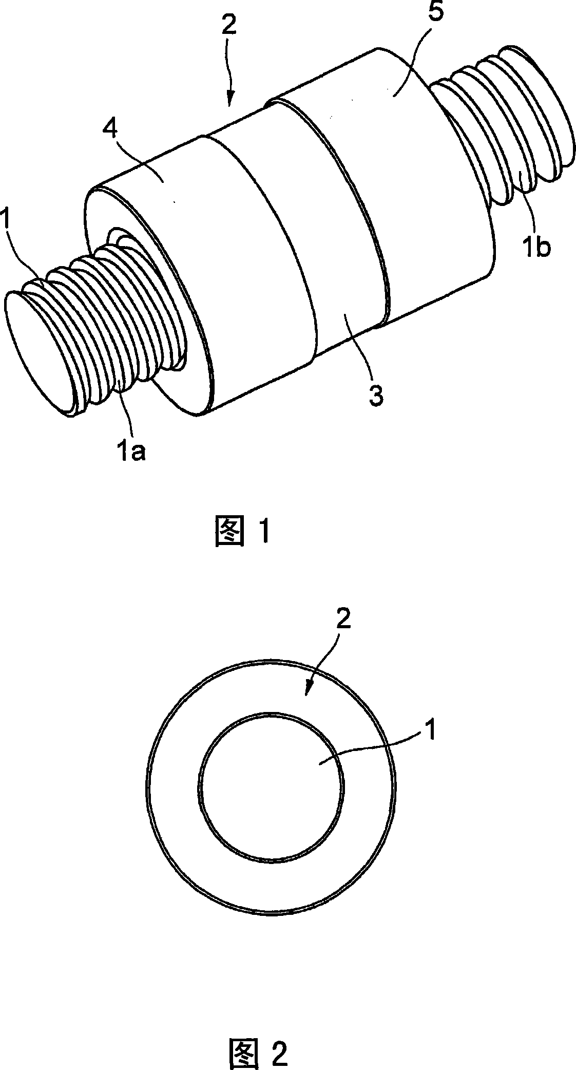
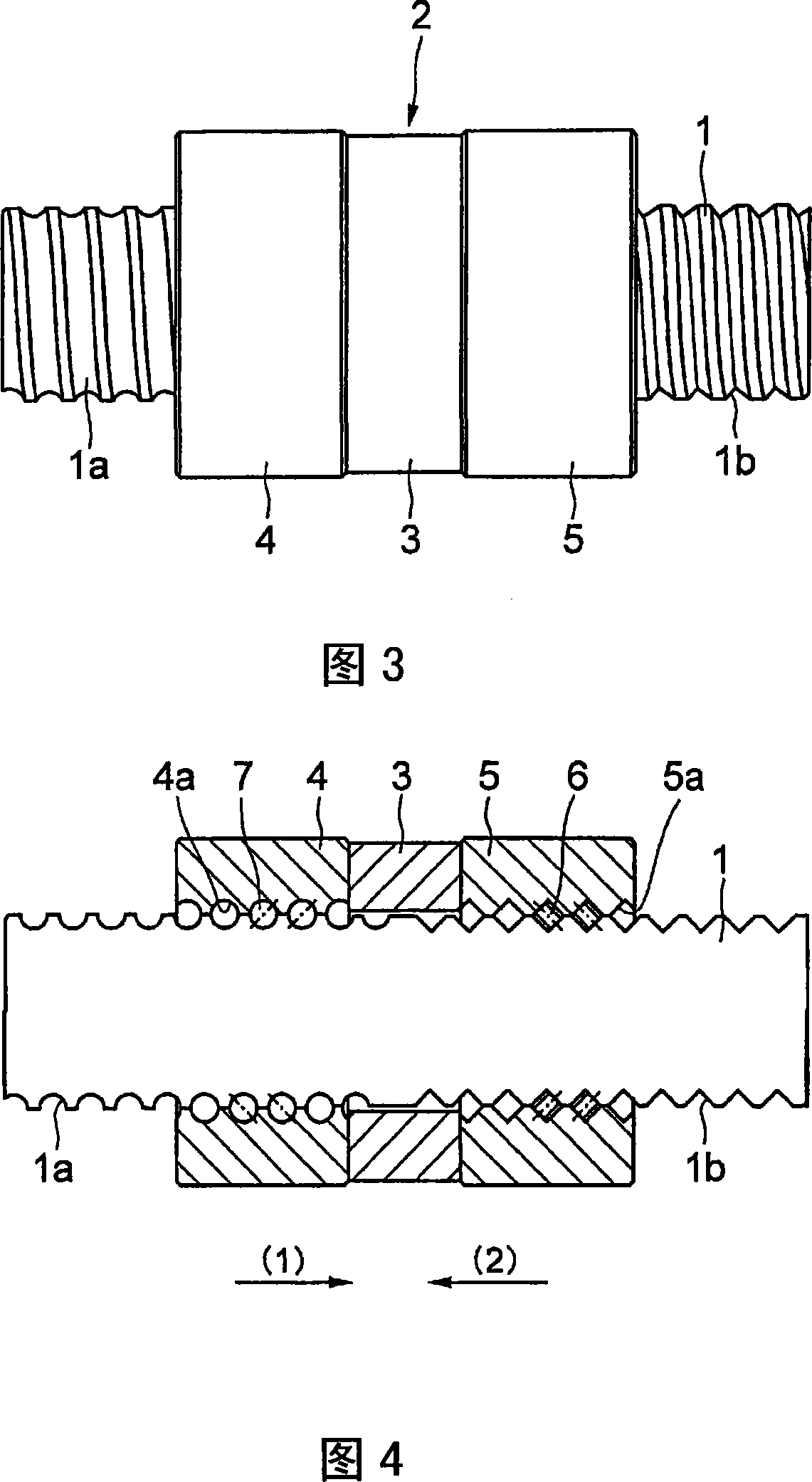
[0032]Hereinafter, the present invention will be described in detail with reference to the drawings. 1 to 3 show a screw device according to a first embodiment of the present invention. 1 shows a perspective view of the screw device, FIG. 2 shows a front view, and FIG. 3 shows a side view, respectively. In Figures 1 to 3, symbol 1 is a threaded shaft, and symbol 2 is a connecting nut. The connecting nut 2 is composed of a ball nut 4 and a roller nut 5 connected via a washer 3 .

[0033] The threaded shaft 1 is formed with both a helical ball rolling groove 1a in which the balls roll and a roller rolling groove 1b in which the rollers roll. The threaded shaft 1 is divided into a ball rolling groove region in which only the ball rolling groove 1a is formed and a roller rolling groove region in which only the roller rolling groove 1b is formed along its axial direction.

[0034] The ball nut 4 of the connection nut 2 faces the ball rolling groove 1 a of the threaded shaft 1 . ...


PUM


Abstract

A screw device so designed as to receive a large load in one axial direction of a screw shaft and receive only a small load in the opposite direction. The screw device comprises the screw shaft (1) having a spiral ball rolling groove (1a) for rolling balls (7) formed in the outer peripheral surface thereof and a spiral roller rolling groove (1b) for rolling rollers (6) formed in the outer peripheral surface thereof, a nut (4) for balls having a spiral ball rolling groove (4a) facing the ball rolling groove (1a) of the screw shaft (1) formed in the inner peripheral surface thereof, a nut (5) for rollers having a spiral roller rolling groove (5a) facing the roller rolling groove (1b) of the screw shaft (1) formed in the inner peripheral surface thereof, the plurality of balls (7) arranged between the screw shaft (1) and the nut (4) for balls, and the plurality of rollers (6) arranged between the screw shaft (1) and the nut (5) for rollers. The nut (4) for balls and the nut (5) for rollers are connected to each other in the axial direction.

Description

technical field [0001] The invention relates to a screw device in which a rolling body is sandwiched between a threaded shaft and a nut so as to be capable of rolling motion. Background technique [0002] A ball screw with rolling balls interposed between a threaded shaft and a nut can reduce the coefficient of friction when the threaded shaft rotates with respect to the nut compared to a screw in sliding contact, so it can be applied to a positioning mechanism of a machine tool , automotive steering gear, guides, sports screws and other fields. For the ball screw, the helical ball raceway groove of the threaded shaft and the ball raceway groove of the nut are aligned at the same position, a plurality of balls are put into the resulting groove, and the nut is formed on the nut for use. Ball circulation circuit. [0003] On the other hand, although it has not progressed to a practical level, in recent years, in order to increase the allowable load, a roller screw using roll...

Claims


Application Information

Patent Timeline
Patent Type & Authority Applications(China)
IPC IPC(8): F16H25/24F16H25/22
CPCF16H25/2209Y10T74/19744F16H2025/2481F16H25/2247Y10T74/18728F16H2025/2271Y10T74/19791
Inventor 吉田明正上杉正和西村健太郎藤田聪永井知荒居宏之
Owner THK CO LTD
Learn More