Cold flow passage multi-mould-hole mould flow passage balance structure

A balanced structure, multi-cavity technology, applied in the field of mold manufacturing, can solve the problems of lowering the quality of the finished product, slow filling of the outer cavity, and fast filling of the inner cavity.

Inactive Publication Date: 2008-07-02
SUZHOU SAMSUNG ELECTRONICS CO LTD
View PDF0 Cites 11 Cited by
  • Summary
  • Abstract
  • Description
  • Claims
  • Application Information

AI Technical Summary

Problems solved by technology

As a result, the inner cavity is filled faster and the outer cavity is filled slower
The effects of this flow imbalance can sometimes be significant, seriously reducing the quality of the finished product

Method used


Image

  • Cold flow passage multi-mould-hole mould flow passage balance structure
  • Cold flow passage multi-mould-hole mould flow passage balance structure
  • Cold flow passage multi-mould-hole mould flow passage balance structure

Examples


Embodiment Construction

[0022] The present invention will be further described below in conjunction with the embodiments shown in the accompanying drawings.

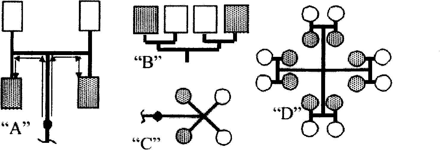
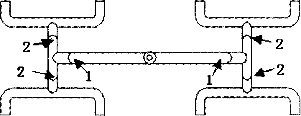
[0023] see Figure 2-9 , the cold runner multi-cavity mold runner balance structure, including the main channel and the runner; also includes the turning structure, the turning structure is set at the junction between the main channel and the runner.

[0024] The turning structure is a circular arc surface structure; a natural arc transition is adopted between the turning structure and the main flow channel and the flow distribution channel. Such as Figure 9 shown.

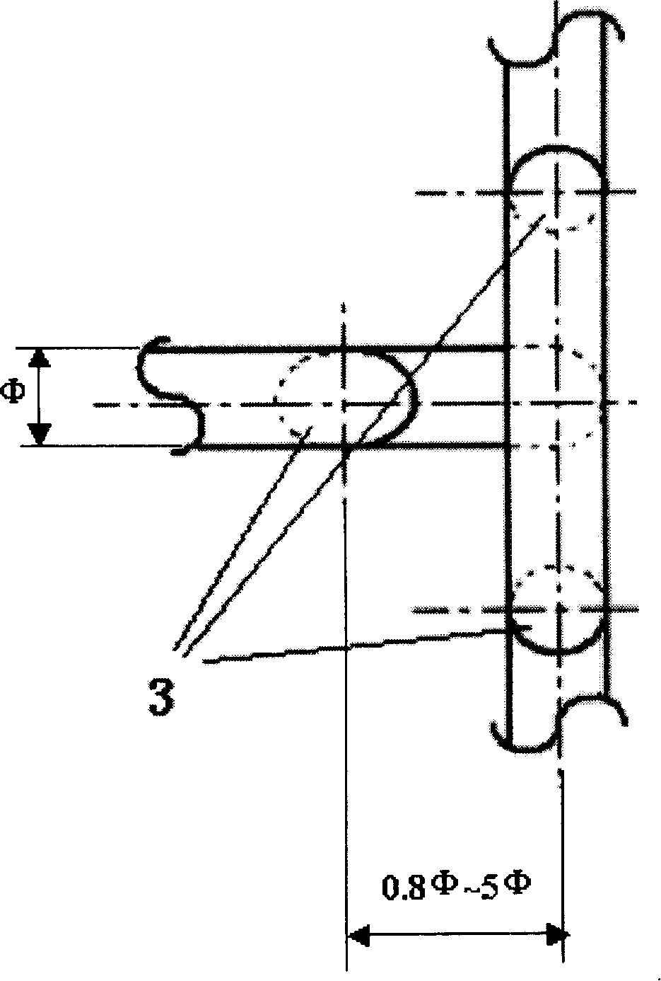
[0025] The diameter of the flipping structure is 1 to 3 times the diameter of the channel where the structure is located, such as Figure 5 shown.

[0026] The length of the flip structure is 0.8 to 5 times the diameter of the flow channel; generally 1.5 to 5 times; as image 3 shown.

[0027] The translational height of the axis line of the turning structure is 0.5 to 1.5 t...


PUM


Abstract

The invention provides a die flow passage balance structure with cold flow passage and a plurality of die cavities, comprising a main flow passage, a branch flow passage and a turnover structure. The turnover structure is arranged at the joint between the main flow passage and the branch flow passage. The turnover structure is a round arc structure. Natural arc transition is adopted between the turnover structure and the main flow passage and the branch flow passage. The diameter of the turnover structure is 1-3 times of the diameter of the flow passage where the structure is positioned and the length thereof is 1.5-5 times of the diameter of the flow passage; the translation height of the axis line is 0.5-1.5 times of the diameter of the flow passage. Smelting glue passes through the turnover structure; the layer distribution state of all characteristics of original smelting glue on the flow passage diameter section is disordered and re-mixed; in the turnover structure, the shearing rate, temperature and viscosity of the smelting glue reach uniform state temporality before entering a next flow passage and flow non-balance state can be eliminated after the smelting glue reaches the next flow passage, thus reaching the balanced characteristics such as consistent pressure, temperature and viscosity of all die cavities, etc. and leading the quality of all die cavity products to tend to consistency.

Description

technical field [0001] The invention belongs to the field of mold manufacturing, and relates to a runner balance technology, in particular to a cold runner multi-cavity mold runner balance technology. Background technique [0002] On the existing cold runner multi-cavity plastic mold, even under the completely symmetrical and balanced runner design of geometric dimensions, there will still be flow imbalance. Because, on the cold-runner multi-cavity plastic mold, the melt properties of the axisymmetric melt in the main channel become asymmetrical after entering the secondary runner. As a result, the inner cavity fills faster and the outer cavity fills slower. The effects of this flow imbalance can sometimes be quite pronounced, seriously degrading the quality of the finished product. Contents of the invention [0003] The purpose of the present invention is to provide a cold runner multi-cavity plastic mold runner balance structure, which can solve the flow unbalance phen...

Claims


Application Information

Patent Timeline
Patent Type & Authority Applications(China)
IPC IPC(8): B29C45/27
Inventor 杨春任海涛毛奇峰秦俸吉
Owner SUZHOU SAMSUNG ELECTRONICS CO LTD
Why Eureka
Try Eureka