Drive circuit of LED

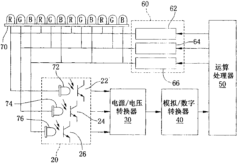
A technology of light-emitting diodes and driving circuits, which is applied in the field of driving circuits, and can solve problems such as high brightness, adjustment of LED groups due to the inability of an arithmetic processor to judge correctly, excessive forward bias voltage of LED lamp group 70, etc.

Active Publication Date: 2010-05-19
MACROBLOCK INC
View PDF6 Cites 0 Cited by
  • Summary
  • Abstract
  • Description
  • Claims
  • Application Information

AI Technical Summary

Problems solved by technology

[0005] However, although the LED lamp group 70 can detect the light brightness of its red LED lamp group, blue LED lamp group and green LED lamp group through three detection LEDs, then the three-color LEDs are turned on by the phototransistors 22, 24 and 26. The brightness values ​​of the lamp groups are sent to the power / voltage converter 30 respectively, but the phototransistors 22, 24 and 26 detect the brightness values ​​of the three-color LED lamp groups at the same time, and then synchronously send them to the power / voltage converter 30, when the LED lights When the number of lamp groups in the group 70 increases and the number of light bulbs in the lamp group increases, the number of corresponding matching phototransistors also increases. In this way, not only will the forward bias voltage (Vf) of the LED lamp group 70 be too large, but also When there are multiple light bulbs in the LED light group 70 or the light bulbs in different light groups have abnormal conditions, the arithmetic processor 50 cannot correctly judge and adjust the required light brightness compensation value of the LED and other groups.
[0006] In addition, the forward bias voltage (Vf) of the LED will change with the time and temperature of the LED. For example, when the temperature rises, the forward bias voltage (Vf) will drop. When driving an LED, when the forward bias voltage drops, the voltage used to emit light will increase, and the resulting brightness will be more than expected; on the contrary, if the forward bias voltage rises, it will fall on the driver IC (integrated circuit) As the voltage increases, the voltage used to emit light becomes smaller, so the resulting brightness is also smaller, which is a challenge for occasions that require stable brightness. In addition, the aforementioned forward bias voltage changes for the driver IC. will also change

Method used


Image

  • Drive circuit of LED
  • Drive circuit of LED
  • Drive circuit of LED

Examples


Embodiment Construction

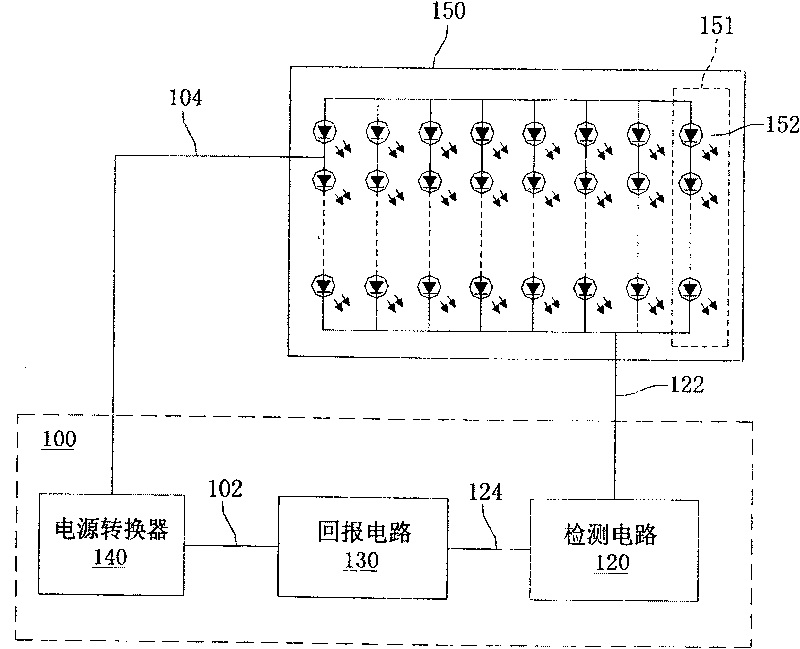
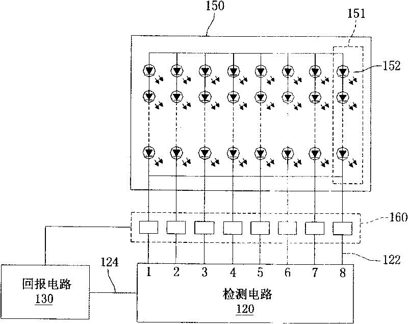
[0041] Please refer to figure 2 , which is a circuit block diagram of the first embodiment of the present invention. It can be seen that the driving circuit 100 of the light emitting diode of the present invention is used to drive a light emitting diode group 150. Diode strings 151 are formed (eight LED strings 151 constitute a LED group 150 in the figure), and each LED string 151 is formed by a plurality of LEDs 152 connected in series, and the drive circuit 100 is driving the LED group 150, it can be driven by providing a constant voltage or constant current, and the driving circuit 100 of the present invention is driven by a constant voltage, and can be driven to emit light all at once, and can also selectively drive a specific LED string 151 to emit light, and By repeatedly driving each LED string 151 sequentially, each LED string 151 can be driven. At the same time, if the switching speed is fast enough, for example, when the switching time is less than 1 / 30 second, huma...


PUM


Abstract

The invention provides a driving circuit of a light emitting diode (LED) for driving a plurality of LEDs to emit light. The LEDs are connected serially into a plurality of LED series. The driving circuit comprises a power converter, a detection circuit and a return circuit. The power converter provides a driving voltage to the LED series. The detection circuit detects the voltage of each LED series, makes a comparison between the voltage of each LED series and a scheduled reference voltage to find out whether the voltage is different from the reference voltage (that is, the LED series work ina non-scheduled condition), and sends a detection signal to the return circuit. The return circuit receives detection signal and outputs a control signal to the power converter so that the power converter adjusts the driving voltage in respond to the control signal to keep the LED series in a normal operation state.

Description

technical field [0001] The invention relates to a driving circuit of a light emitting diode, in particular to a driving circuit of a light emitting diode used to drive a plurality of light emitting diode circuits connected in parallel and in series. Background technique [0002] Light Emitting Diodes (LEDs) have been widely used in daily life in recent years, such as displays, home appliances, automotive electronic components, and lighting fixtures. Taking a display as an example, the existing display includes three color light groups: a red (R) light group, a green (G) light group and a blue (B) light group. Before assembling the three-color light group, it must be determined whether the LED bulbs in each color light group have the same characteristics. The test method is to pass the same current first, and then according to the light intensity, color, forward bias (Vf) Whether they are similar can be classified into three-color light groups. However, after the monitor ha...

Claims


Application Information

Patent Timeline
Patent Type & Authority Patents(China)
IPC IPC(8): H05B33/08H05B44/00
Inventor 林益胜
Owner MACROBLOCK INC
Why Eureka
Try Eureka