Scale removing system
A scale and water treatment technology, applied in the field of scale systems, can solve problems such as the decrease of electrode life
- Summary
- Abstract
- Description
- Claims
- Application Information
AI Technical Summary
Problems solved by technology
Method used
Image

Examples
Embodiment 1
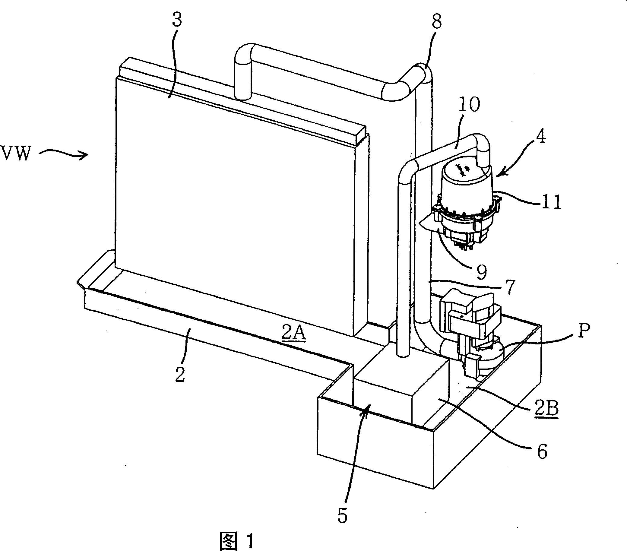
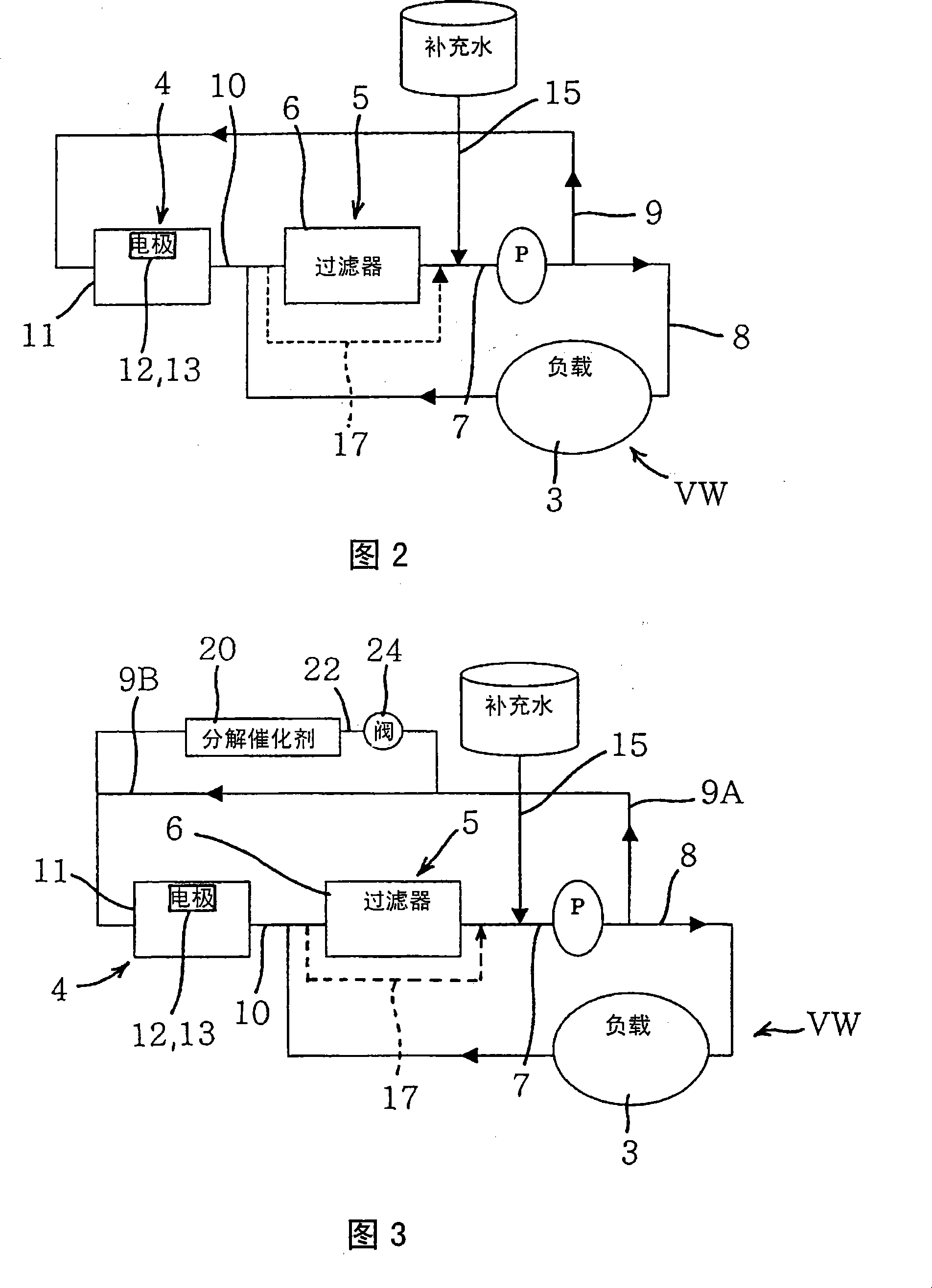
[0032] FIG. 1 is a schematic configuration diagram of a scale recovery system according to an embodiment of the present invention, and FIG. 2 is a system diagram of the scale recovery system of FIG. 1 . In this example, the scale recovery system of the present invention is applied to the air sterilizing device VW. Therefore, the load of the present invention corresponds to the battery of the air cleaning device VW.
[0033] The air sterilizing device VW of the present embodiment possesses: the water receiving tank 2 as the water storage part; the battery 3 (equivalent to the load of the present invention) that is arranged on the water receiving tank 2; the electrolyzer 11; (The electrodes are not shown in FIG. 1 ) and other components of the electrolytic treatment mechanism 4; the scale recovery mechanism 5 provided on the downstream side (outlet side) of the electrolytic treatment mechanism 4; and the pump P for circulating water (water to be treated).
[0034] The battery 3...
Embodiment 2
[0063] Next, a scale recovery system of another embodiment (second embodiment) will be described using FIG. 3 . Like the first embodiment above, in this embodiment, the scale recovery system is applied to the air sterilization device VW, and FIG. 3 is a system diagram of the scale recovery system of this embodiment. In addition, in FIG. 3 , parts marked with the same symbols as those in FIG. 1 and FIG. 2 exert the same or similar effects and functions, and description thereof will be omitted here.
[0064]In FIG. 3 , 20 is a decomposition catalyst as a hypochlorous acid decomposition mechanism. The decomposition catalyst 20 of this embodiment is composed of a catalyst for decomposing hypochlorous acid in the water to be treated, and is arranged on the pipe 22 . The pipe 22 is a pipe branched from the pipe 9A. One end branched from the pipe 9A passes through the decomposition catalyst 20, and the other end is connected to the upstream side (inlet side) of the electrolytic trea...
Embodiment 3
[0083] And, as the decomposition catalyst 20, for example, in the case of using a thermal catalyst such as nickel oxide, that is, hypochlorous acid in the water to be treated is not decomposed at normal temperature, and the catalytic effect is exerted by heating to a predetermined temperature. In the case of a hypochlorous acid catalyst, instead of providing the piping 22 and the three-way valve 25 of the above-mentioned embodiment 2, a decomposition catalyst 20 may be provided on the piping 9 as shown in FIG. 6 . In this case, the decomposition catalyst 20 is equipped with a heating mechanism (for example, a heater 27 ) capable of heating the decomposition catalyst 20 to a predetermined temperature. And, in the case of using nickel oxide as the decomposition catalyst 20, the decomposition effect is exerted by heating to 40° C. to 70° C., so it is necessary to control the energization of the heater 27 so as to heat the nickel oxide to a temperature of 40° C. to 70° C. .
[00...
PUM
 Abstract
Description
Claims
Application Information
 - R&D
- Intellectual Property
- Life Sciences
- Materials
- Tech Scout
- Unparalleled Data Quality
- Higher Quality Content
- 60% Fewer Hallucinations
Browse by: Latest US Patents, China's latest patents, Technical Efficacy Thesaurus, Application Domain, Technology Topic, Popular Technical Reports.
© 2025 PatSnap. All rights reserved.Legal|Privacy policy|Modern Slavery Act Transparency Statement|Sitemap|About US| Contact US: help@patsnap.com