Coupling piece for a detachable connection of containers

A technology of coupling elements and disassembly connections, applied in the field of coupling elements, can solve problems such as high cost

Inactive Publication Date: 2008-08-06
MACGREGOR CONVER
View PDF0 Cites 7 Cited by
  • Summary
  • Abstract
  • Description
  • Claims
  • Application Information

AI Technical Summary

Problems solved by technology

This means that there is a high...

Method used


Image

  • Coupling piece for a detachable connection of containers
  • Coupling piece for a detachable connection of containers
  • Coupling piece for a detachable connection of containers

Examples


Embodiment Construction

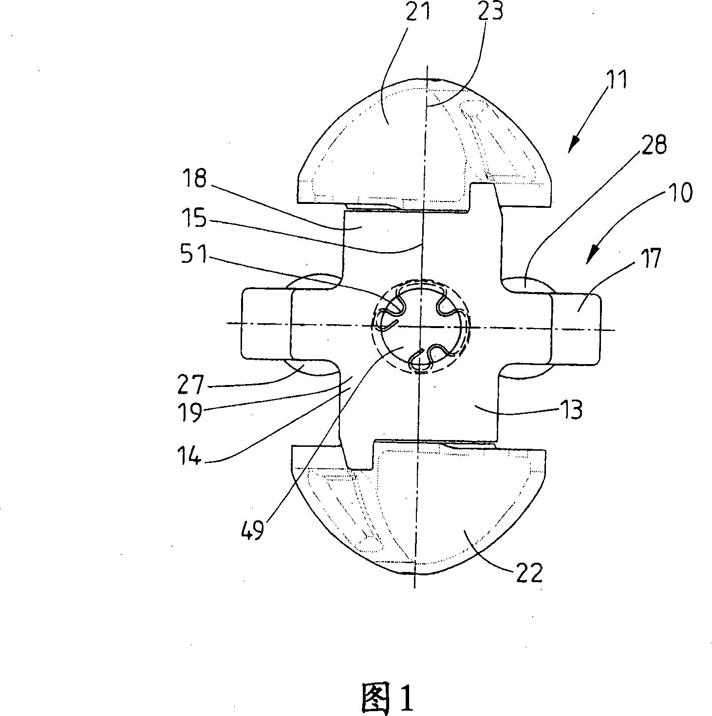
[0023] Two embodiments of coupling elements shown are so-called semi-automatic twist locks for the semi-automatic connection of vertically stacked containers (not shown in the figures). The coupling element locks automatically as soon as the containers to be connected are positioned in a stack. Only manual unlocking of the coupling element is required.

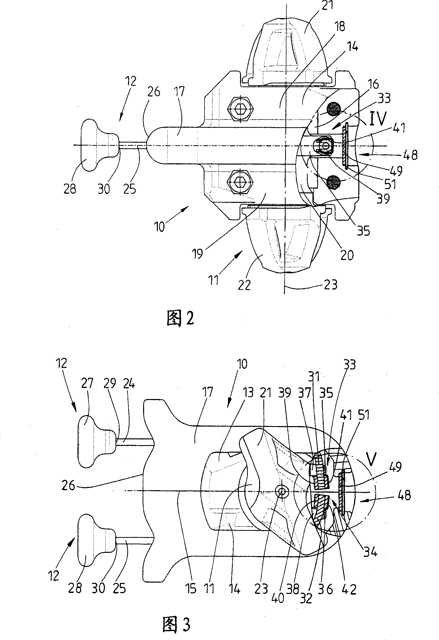
[0024] Figures 1 to 5 show a semi-automatic coupling element consisting of the following necessary parts: a chamber 10, a locking bolt 11, and two actuating devices 12, in this embodiment the two actuating devices 12 are identical.

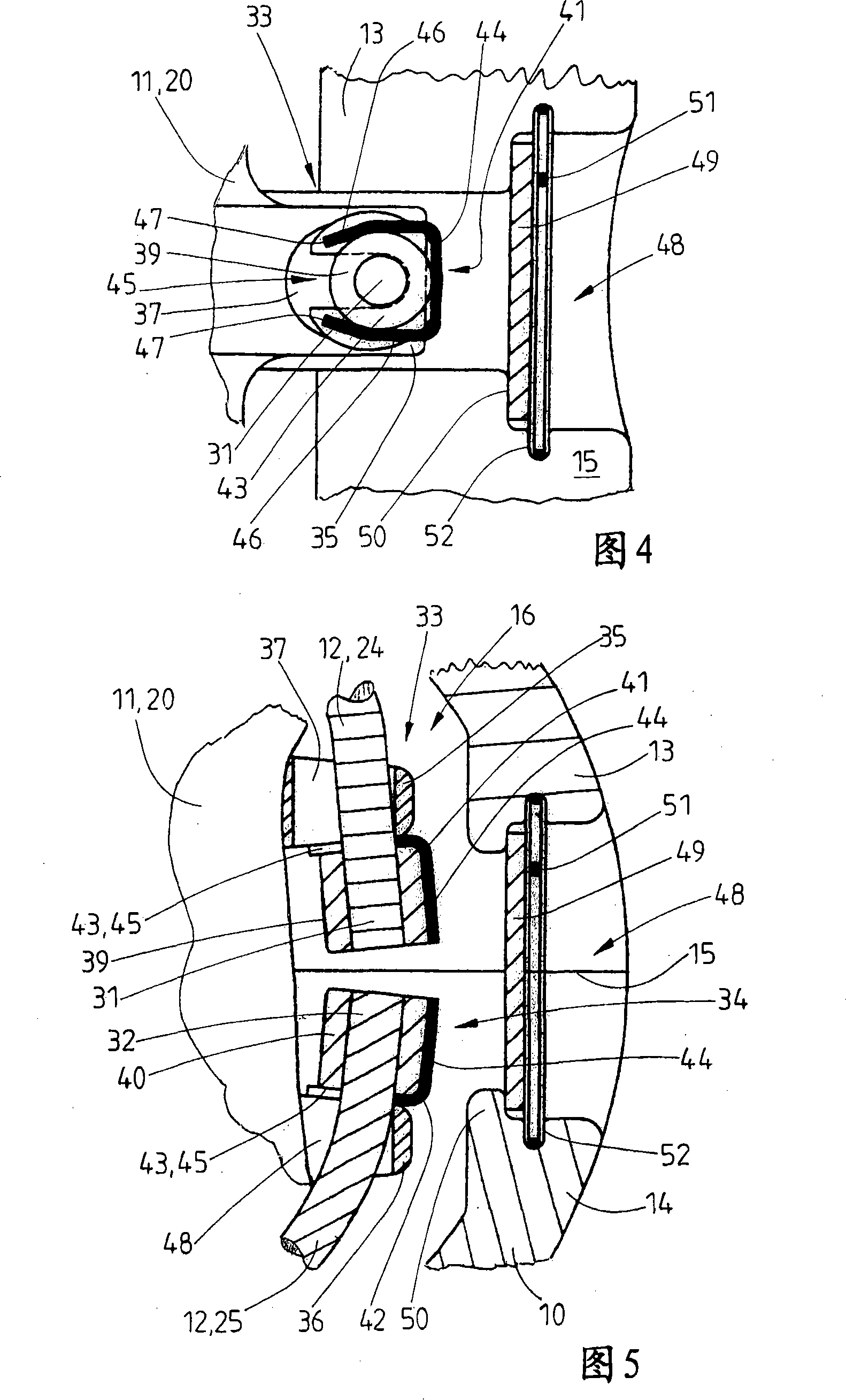
[0025] The chamber 10 of the coupling element shown here is designed in two parts. It comprises two half chambers 13 and 14 which are screwed together along a central dividing plane 15 . The separating surface 15 extends longitudinally through the center of the through-opening 16 in the chamber 10 . Furthermore, with regard to the use position of the coupling element, which is shown in FIGS. 1...


PUM


Abstract

A coupling element for container connection has at least one actuating device (12) to rotate a locking bolt (11). When replacing a defective or worn actuating device (12), the existing coupling element must be removed. The invention relates to a coupling element, wherein the at least one actuating device (12) is detachably connected to a locking screw (11). For this purpose, inserting action holding means ( 41 , 42 ) are used, which can be accessed from outside the chamber ( 10 ) through an opening ( 48 ) of the chamber ( 10 ). In the case of the coupling element according to the invention, the actuating means (12) can be replaced directly without dismantling the chamber (10).

Description

technical field [0001] The invention relates to a coupling element according to the preamble of claim 1 for the detachable connection of containers, in particular containers on flat ships. Background technique [0002] The types of coupling elements mentioned in the introduction are often referred to as "twist locks" in the field. These coupling elements are mainly used for interconnecting containers transported on flat boats. This prevents displacement of the containers relative to each other during the movement of the ship. [0003] The coupling element comprises a locking bolt with coupling plates at opposite ends thereof. The gussets snap behind the slots of the corner fittings of the containers to be connected. Between the coupling plates, the locking bolt has a central part, via which the locking bolt is mounted rotatably in the cavity of the coupling element. At least for the purpose of unlocking the coupling element, the locking bolt is turned by an actuating dev...

Claims


Application Information

Patent Timeline
IPC IPC(8): B65D90/00
CPCB65D90/0013F16B7/00F16B7/10
Inventor J·魏伦贝格T·盖本赫纳
Owner MACGREGOR CONVER
Why Eureka
Try Eureka