Face cutter for machining fibre-reinforced materials such as carbon-fibre-reinforced plastics (cfrp)

一种纤维、塑料的技术,应用在CFK端铣刀领域,能够解决聚酯丝线散开等问题

Active Publication Date: 2015-08-12
HUFSCHMIED ZERSPANUNGSSYST
View PDF17 Cites 5 Cited by
  • Summary
  • Abstract
  • Description
  • Claims
  • Application Information

AI Technical Summary

Problems solved by technology

[0002] When milling and drilling fiber-reinforced materials such as CFK, GFK (glass fiber reinforced plastics) and polyester thread-reinforced plastics, there is a problem when using conventional cutting tools When processing workpieces made of this material, individual fibers are usually pulled out or polyester threads are unraveled (Aufspleissen)

Method used


Image

  • Face cutter for machining fibre-reinforced materials such as carbon-fibre-reinforced plastics (cfrp)
  • Face cutter for machining fibre-reinforced materials such as carbon-fibre-reinforced plastics (cfrp)

Examples


Embodiment Construction

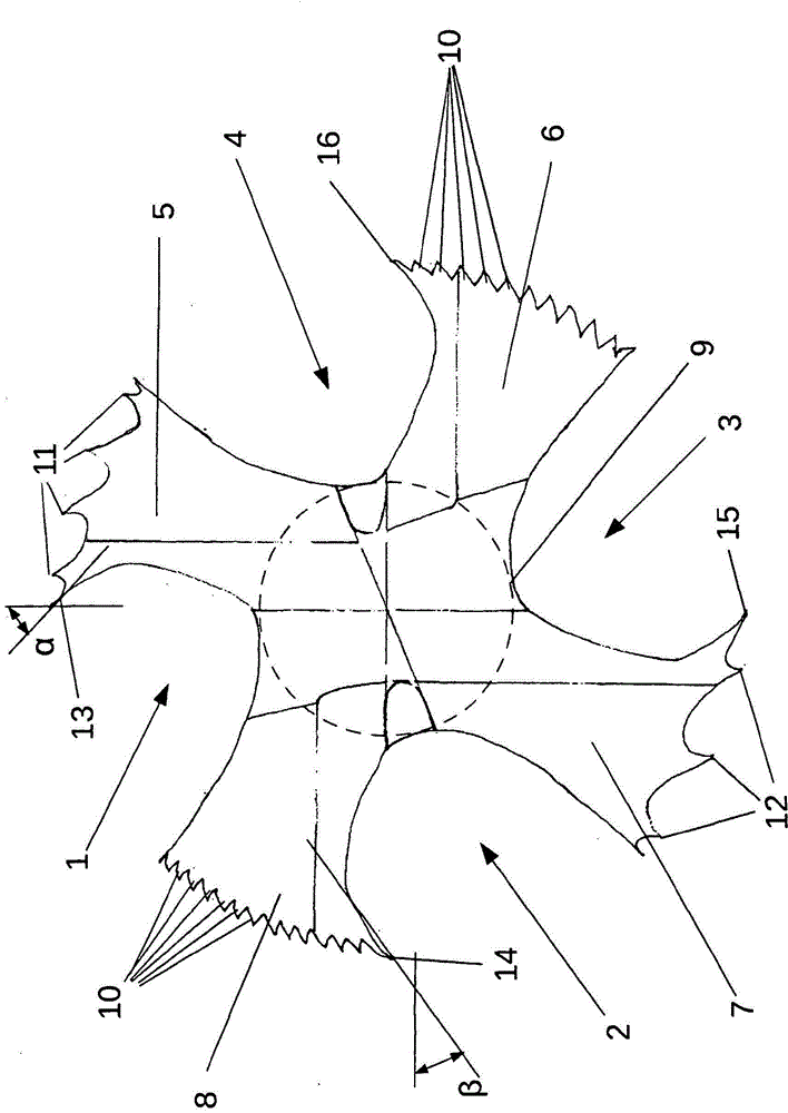
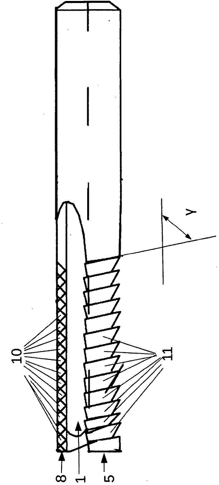
[0029] The end mill shown in the figure has four equidistantly spaced flutes 1 , 2 , 3 , 4 which divide the inserts 5 , 6 , 7 , 8 equidistantly around a cylindrical core section 9 . spaced apart from each other. Cutting edges 13, 14, 15, 16 on acute-angled cutting wedges are respectively provided on the outer edges of the blades 5, 6, 7, 8 towards the peripheral sides of the front flutes 1, 2, 3, 4, in, figure 1 The main rake angle α on the two blades 5, 7 shown in , is the same size, and the main rake angle β on the two blades 6, 8 is the same size, but it is drawn slightly exaggerated in the figure, while in the actual situation down about 8°.

[0030] Pyramidal teeth 10 are machined here on the two opposite inserts 6 , 8 in their peripheral working area extending from the tool tip along the tool axis, in such a way that they follow intersecting lines on the outer circumferential surface toward the insert 6 . , Grinding triangular grooves in the peripheral surface of 8 . ...


PUM


Abstract

The invention concerns a machining tool for machining fibre-reinforced materials such as CFRP, glass-fibre-reinforced plastics or plastics reinforced with polyester threads. The machining tool comprises a plurality of flutes (1, 2, 3, 4) which distance lands (5, 6, 7, 8), disposed about a cylinder core segment (9), from each other in the peripheral sense. At least one of the lands (6, 8) is designed as a premachining land (6, 8) and at least one other of the lands (5, 7) is designed as a postmachining land (5, 7), each comprising a peripheral working region extending along, or with a twist and in the form of a helical segment about, the tool axis. The working region of each premachining land (6, 8) is designed as a peripheral file with a plurality of teeth (10) which are incorporated in a cylinder surface segment-shaped outer surface of the working region, and provided in the working region of each postmachining land (5, 7) is a number of sharp cutting edges (11, 12, 13, 15) extending parallel to or with a twist and in the form of a helical segment about the tool axis. The invention is characterized in that the number of sharp cutting edges (11, 12, 13, 15) on at least one postmachining land (5, 7) comprises a plurality of cutting edges (11, 12) each provided on a peripheral casing groove, the casing grooves being incorporated in a cylinder surface segment-shaped outer face of the working region, parallel to each other and at a pitch relative to the flute (1, 3) leading at least one postmachining land (5, 7).

Description

technical field [0001] The invention relates to an end mill for machining fiber-reinforced materials, such as CFK (carbon fiber reinforced plastic), according to the preamble of claim 1 . Background technique [0002] When milling and drilling fiber-reinforced materials such as CFK, GFK (glass fiber reinforced plastics) and polyester thread-reinforced plastics, there is a problem when using conventional cutting tools When processing workpieces made of this material, it is common for individual fibers to be pulled out or polyester threads to unravel (Aufspleissen). That is to say that individual fibers are pulled out from the edge of the processing point and other fibers are pressed against the edge of the processing point as the tool passes, so that these fibers are first cut at the ends protruding beyond the edge of the processing point and thus The edges are highlighted after processing. As a rule, after pre-machining or rough-machining, further machining processes, ie f...

Claims


Application Information

Patent Timeline
Patent Type & Authority Applications(China)
IPC IPC(8): B23C5/10B23B51/08
CPCB23C2220/605B23C2210/326B23B2226/275B23C5/10B23C2226/27B23B51/08B23C2210/0485Y10T407/1815B23C2210/321B23C2210/40
Inventor R·胡夫施米德
Owner HUFSCHMIED ZERSPANUNGSSYST
Why Eureka
Try Eureka