Actuating handle

A technology for operating handles and operating components, which is applied in the field of operating handles and can solve problems such as expensive assembly

Active Publication Date: 2015-11-25
ALMAR
View PDF5 Cites 5 Cited by
  • Summary
  • Abstract
  • Description
  • Claims
  • Application Information

AI Technical Summary

Problems solved by technology

However, a disadvantage in the actuating handles known from the prior art is the complex assembly, since the actuating part must first be pushed onto the drive element, and then the screw must be turned through the actuating element by means of a tool, such as for example a screwdriver or an Allen key. the through hole of the component until the screw makes contact with the driving element

Method used


Image

  • Actuating handle
  • Actuating handle
  • Actuating handle

Examples


Embodiment Construction

[0025] In the description that now follows, the same reference numerals designate the same components or the same features, so that in order to avoid repeated descriptions, the description of the components with respect to the figures also applies to the other figures.

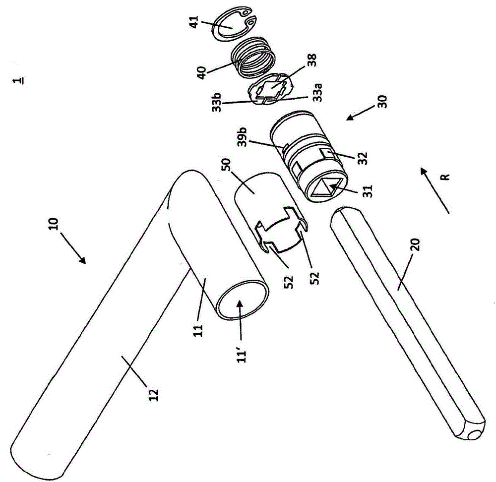
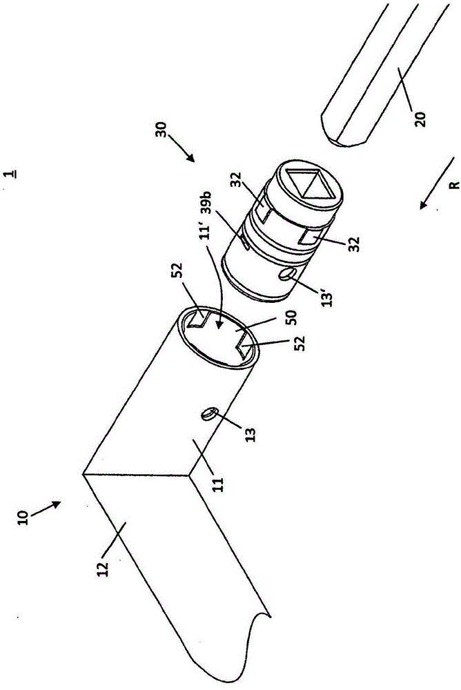
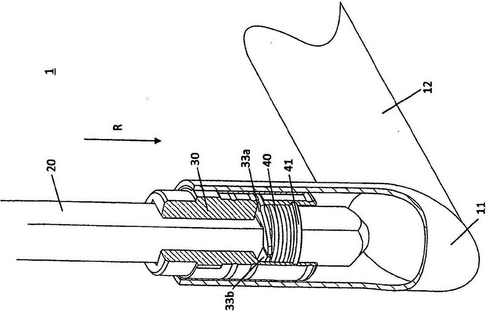
[0026] Depend on figure 1 and 2 It can be seen that the construction of the joystick 1 according to the invention, wherein, in figure 1 shows the joystick 1 in the disassembled state, while in figure 2 shows the joystick in a partially assembled state. The operating handle 1 comprises an actuating part 10 which, in the exemplary embodiment shown, is designed as a door handle 10 with a neck section 11 and a handle section 12 . The neck section 11 is hollow and has a recess 11 ′ for receiving the fastening sleeve 50 and the receiving sleeve 30 .

[0027] The receiving sleeve 30 has a receiving opening 31 for receiving the driver element 20 . In the exemplary embodiment shown, the entraining element 20 is d...


PUM


Abstract

An actuating handle for wing-like structural elements, such as windows, doors and the like, comprises a handling part (10), a driver element (20), a receiving sleeve (30), a clamping device for clamping the driver element (20) in the receiving sleeve (30) and a force-exerting device (40) acting on the clamping device. The clamping device comprises a first clamping frame (33a) and a second clamping frame (33b) which are arranged opposite each other and on both sides of the driver element (20) and are pivotable in opposite pivoting directions. The clamping frames (33a, 33b) exert a clamping force on the driver element (20), the clamping force preventing the handling part (10) from being pulled off the driver element (20).

Description

technical field [0001] The invention relates to an operating handle for fan-shaped structural elements such as windows, doors, etc. according to the preamble of claim 1 . Background technique [0002] The operating handle is used, for example, to open and close windows or doors and comprises an actuating part, for example in the form of a door handle, which is non-rotatably connected to an actuating element, for example in the form of a quadrilateral pin. By turning the door handle, the quadrangular pin, which is connected in a rotationally fixed manner to the door handle, likewise turns and actuates the door lock, for example. [0003] The driver must also generally transmit the axial tensile and compressive forces introduced by the actuating part to the fan-shaped structural element because, for example, the door is pulled open after opening the door handle by means of the actuating handle. In this case, the connection between the actuating part and the driver element mus...

Claims


Application Information

Patent Timeline
Patent Type & Authority Applications(China)
IPC IPC(8): E05B3/04E05B3/00
CPCE05B3/00E05B3/04E05B63/006E05B2003/006
Inventor S·马蒂内利P·马蒂内利
Owner ALMAR
Why Eureka
Try Eureka