Device for replacing mobile device lens

A mobile device and lens technology, applied in installation, camera body, optics, etc., can solve the problems of inability to replace lenses according to different needs, inability to take long-distance or wide-angle shooting, and high production costs, and achieve easy portability and improved Camera function, small size effect

Active Publication Date: 2011-05-04
ASUSTEK COMPUTER INC
View PDF4 Cites 4 Cited by
  • Summary
  • Abstract
  • Description
  • Claims
  • Application Information

AI Technical Summary

Problems solved by technology

[0002] Traditional mobile devices with camera functions (such as mobile phones, personal digital assistants, PDAs, game consoles, etc.) all have the lens (group) of the lens built into the device, and the focal length can only be adjusted manually or mechanically. Different replacement lenses, and its production cost is relatively high
In addition, the mid-to-low price models on the market generally have poor camera performance and no zoom function due to cost or volume constraints. Due to the fixed focal length of the lens, they can only shoot objects within a specific range, and cannot take long-distance or wide-angle shots.

Method used


Image

  • Device for replacing mobile device lens
  • Device for replacing mobile device lens
  • Device for replacing mobile device lens

Examples


Embodiment 1

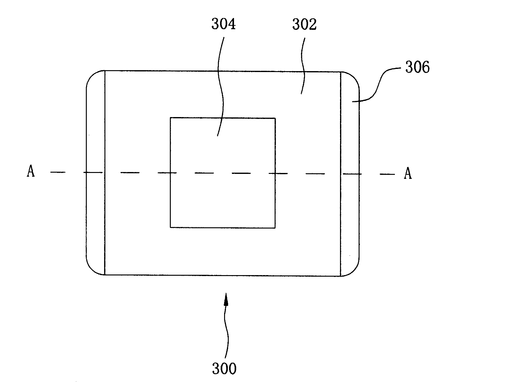
[0027] In a preferred embodiment of the present invention, a buckle device is provided to change the lens of the mobile device. refer to Figure 1A , which is a top view of the fastener device of the present invention, which shows the base 302 , the hole 304 in the center of the base 302 and the slot 306 on one side of the base 302 .

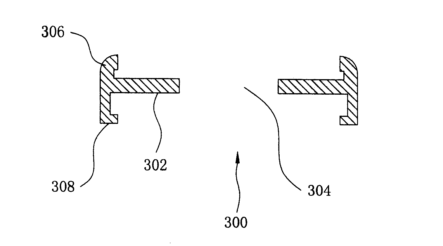
[0028] Figure 1B then show Figure 1A Sectional view along line AA. As shown in the figure, the center of the base 302 of the buckle device 300 has a hole 304 therethrough. There is at least one slot 306 on one side of the base 302 for accommodating a lens. On the other side of the base 302 there is at least one buckle 308 for fixing the buckle device 300 on the mobile device. Wherein, the buckle device is preferably made of elastic plastic.

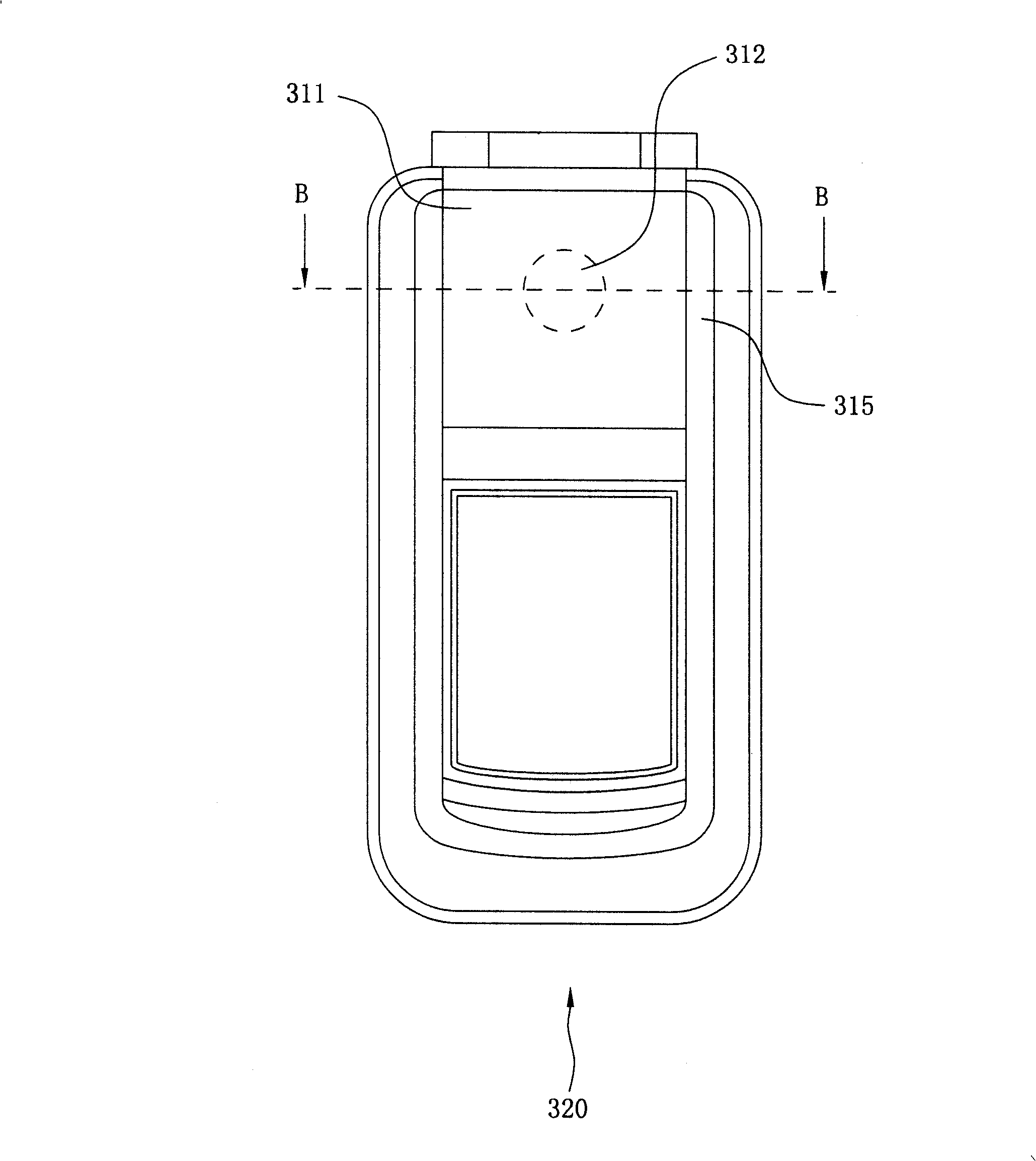
[0029] Please also refer to Figure 2A-2B , which is a structural schematic diagram of a mobile phone, used to help illustrate the use of the buckle device of the present invention. first, Figure ...

Embodiment 2

[0032] In another preferred embodiment of the present invention, a suction device is provided to change the lens of the mobile device. refer to Figure 3A , which is a top view of the adsorption device of the present invention, which shows the base 402 , the hole 404 in the center of the base 402 and the slot 406 on one side of the base 402 .

[0033] Figure 3B then show Figure 3A Sectional view along line CC. As shown in the figure, the center of the base 402 of the adsorption device 400 has a hole 404 penetrating through it. There is at least one slot 406 on one side of the base 402 for accommodating a lens. Wherein, the adsorption device 400 is preferably made of ferromagnetic material, and the adsorption device 400 is fixed on the outside of the lens of the mobile device by magnetic adsorption.

[0034] Please also refer to Figures 4A-4B , which is a structural schematic diagram of a mobile phone, used to help illustrate the use of the buckle device of the present...

Embodiment 3

[0037] In another preferred embodiment of the present invention, a sliding device is provided. The sliding device has a plurality of lenses. By sliding, the required lenses are moved to the front of the lens of the mobile device, so as to change the position of the lens of the mobile device. Effect.

[0038] Such as Figure 5A As shown, the sliding device 500 includes a sliding member 502 for fitting a plurality of lenses 510, and at least one protrusion 504 disposed on the side of the sliding member 502 for fastening with the sliding rail 516 on the side of the moving device 520 , to move along the rail.

[0039] In this embodiment, the user can move the slide device 500 along the slide rail 516 as desired, so that one of the lenses 510 is aligned with the lens 512 of the mobile device ( Figure 5B ), and then change the lens function to obtain various shooting effects.


PUM


Abstract

A device used to replace a camera of a movable device adopts a mode of appending a lens to reach the function of replacing a camera lens besides the camera lens of the movable device. The device is tabled with the required lens firstly, and arranged in the front of the camera lens by using the mode of fastening, magnetic attraction or sliding, then the tabled lens is used to replace the function of the camera lens.

Description

technical field [0001] The present invention relates to a photographic device, and more particularly, the present invention relates to a photographic device for changing the lens of a mobile device. Background technique [0002] Traditional mobile devices with camera functions (such as mobile phones, personal digital assistants PDA, game consoles, etc.) all have the lens (group) of the lens built into the device, and the focal length can only be adjusted manually or mechanically, which cannot be adjusted according to the needs. Different replacement lenses, and its production cost is relatively high. In addition, the mid-to-low price models on the market generally have poor camera performance and no zoom function due to cost or volume constraints. Due to the fixed focal length of the lens, they can only shoot objects within a specific range, and cannot take long-distance or wide-angle shots. Contents of the invention [0003] Therefore, the present invention improves the ...

Claims


Application Information

Patent Timeline
Patent Type & Authority Patents(China)
IPC IPC(8): G03B17/14G03B17/02G02B7/02G03B30/00
Inventor 李易修
Owner ASUSTEK COMPUTER INC
Why Eureka
Try Eureka