Imaging apparatus and reproducing apparatus

A technology of a camera device and a playback device, which is applied in the directions of image communication, TV, color TV components, etc., can solve the problem of not setting a detection unit, etc., and achieve the effect of preventing playback and preventing candid photography.

Active Publication Date: 2008-09-03
VICTOR CO OF JAPAN LTD
View PDF2 Cites 23 Cited by
  • Summary
  • Abstract
  • Description
  • Claims
  • Application Information

AI Technical Summary

Problems solved by technology

[0010] Further, there is the following problem: in the replay device, no detection unit is provided to detect whether the replay image is a replay image of a sneak shot by the camera device in the theater, so that it can be directly replayed

Method used


Image

  • Imaging apparatus and reproducing apparatus
  • Imaging apparatus and reproducing apparatus
  • Imaging apparatus and reproducing apparatus

Examples


Embodiment 1

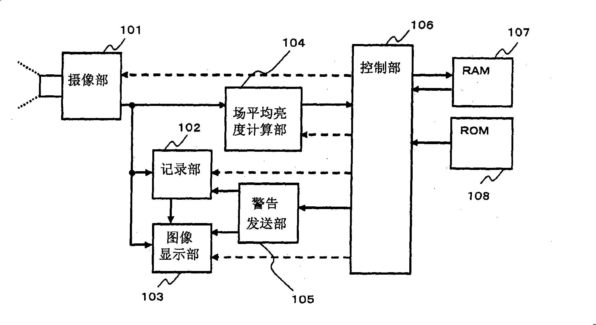
[0083] refer to figure 1 A configuration example of an imaging device applied to Embodiment 1 will be described. The imaging unit 101 converts a captured image into an electrical signal, and performs an optical function such as focusing a lens on a subject. The recording unit 102 writes the captured image on a recording medium such as a magnetic tape, HDD, magnetic disk, memory, or optical disk. Then, the recorded data is deleted according to an instruction from the control unit 106 . The image display unit 103 displays information necessary for shooting, such as time, when taking an image or capturing an image, and displays an image recorded in the recording unit 102 . The field average luminance calculation unit 104 calculates the average luminance of one field (field, field) of the captured image. The warning transmission unit 105 transmits a warning message to the recording unit 102 while displaying a warning message on the image display unit 103 when the control unit 1...

Embodiment 2

[0109] Then refer to Figure 8 A configuration example of an imaging device applied to the second embodiment will be described. The imaging unit 2101 converts a captured image into an electrical signal, and performs an optical function such as focusing a lens on a subject. The recording unit 2102 writes the captured image on a recording medium such as a magnetic tape, HDD, magnetic disk, memory, or optical disk. Furthermore, the recording unit 2102 deletes the recorded data according to an instruction from the control unit 2106 .

[0110] The image display unit 2103 displays information necessary for shooting, such as time, when capturing an image or capturing an image, and displays an image recorded in the recording unit 2102 . The average luminance calculation unit 2104 calculates the average luminance of the field of the captured image, and divides the field to calculate the average luminance. When the control unit 2106 detects a sneak shot of a movie, the warning transm...

Embodiment 3

[0142] Then refer to Figure 17 A configuration example of an imaging device applicable to Embodiment 3 will be described. The imaging unit 3101 converts an image captured by the imaging element 3101 a for imaging into an electrical signal, and also performs an optical function such as focusing a lens on a subject. In addition, it is constituted by a visible light luminance measuring element 3101b used for determination of sneak photography. The visible light luminance measuring element 3101b has a function of converting the luminance of imaging light entering through a lens into an electrical signal.

[0143] The recording unit 3102 writes captured images on a recording medium such as a magnetic tape, HDD, magnetic disk, memory, or optical disk. Then, the recorded data is deleted according to an instruction from the control unit 3106 .

[0144] The image display unit 3103 displays information necessary for shooting, such as time, when taking an image or capturing an image,...


PUM


Abstract

The invention provides an imaging apparatus which can prevent the candid for detecing the imaging signal for shooting the film projected picture in the theater for presenting the film and the line, wherein after the image shot by an image part (101), the average brightness for shooting the image is figured in a field average brightness figuring part. A control part (106) measures the field average brightness of five continuous shooting fields, the candid of the film is detected through judging the ratio of the max brightness and the minimum brightness. When detecting the candid of the film, the warning information is displayed in the image display part (103) by the transmitting part (105), and the recording data of the recording medium is deleted by the recoding part (102), or the warning information and the image are recorded to the recording medium.

Description

technical field [0001] The present invention relates to a camera device for preventing sneak shots in theaters showing movies and other programs, and a playback device for preventing sneak shots from being played back. Background technique [0002] Conventionally, there has been a problem of so-called pirated DVDs and other duplications in which movies and other programs are secretly photographed with camera equipment and illegally duplicated in theaters where movies and other programs are shown. In recent years, along with the rapid improvement of the resolution of imaging devices, devices compatible with HD (High Definition Television: High Definition Television) have appeared, enabling high-quality image capture. In this case, candid photography has further become a big problem. [0003] In this regard, the following proposals have been proposed (for example, with reference to Patent Document 1): the infrared light as the remote control signal of the imaging device is us...

Claims


Application Information

Patent Timeline
Patent Type & Authority Applications(China)
IPC IPC(8): H04N5/225H04N5/76H04N5/91H04N5/913
Inventor 小林一英
Owner VICTOR CO OF JAPAN LTD
Why Eureka
Try Eureka